Posts

Showing posts from April, 2022

Modulation Technique and Density

Image
  Modulation is a technique for converting one form of information to another form. In satellite communications this is the digital conversion to analogue for transmissions over the satellite link. In the modulation process multiple digital bits can be converted in to one analogue symbol. The reverse process is called demodulation. 8PSK Modulation Phase-Shift-Keying (PSK) is commonly used in Sat Comms (BPSK, QPSK, 8PSK and 16APSK). PSK works by varying one or more of the analogue signal characteristics (Amplitude, Frequency and/or Phase). Higher density bits per symbol gives more throughput on the link but will require higher receive signal and transmit power. Binary Phase Shift Keying (BPSK) 1 symbol represents 1 bit of information (0 or 1). Quadrature Phase Shift Keying (QPSK) 1 symbol represents 2 bits of information (00, 01, 10 or 11). 8 Phase Shift Keying (8PSK) 1 symbol represents 3 bits of information (000, 001 …. 110,111). 16-Ary Amplitude and Phase Shift Keying (16APSK) 1 ...

SYMBOL RATE CALCULATION

Image
  Symbol Rate Calculator Tool Data Rate (DR): bps kbps Mbps Gbps Modulation Factor (m): BPSK QPSK 8PSK 8QAM 16QAM 32QAM 64QAM 128QAM 256QAM Forward Eror Correction (FEC): 1/4 1/3 2/5 1/2 3/5 2/3 3/4 4/5 5/6 8/9 CALCULATE Symbol Rate: Symbol & Baud Rate Information Symbol Rate or Baudrate is the number of symbol changes per second made to the signal. According to the modulation coding method (MODCOD) used each symbol can represent 1, 2, 3, 4, etc. bits of transmission rate data. So for example, when BPSK modulation is used the symbol rate is the same as the bit rate because 1 bit of data is transmitted per symbol. The rate at which symbols are transmitted is the baud rate. SR  – Symbol Rate FEC  –  Forward Error Correction DR  – Data Rate m  – Modulation Factor sps  – Symbols per second Bits per Symbol ( modulation  factor) BPSK = 1 QPSK = 2 8PSK = 3 8QAM or 8APSK= 3 16QAM or 16 APSK = 4 32QAM or 32 APSK = 5 64QAM or 64 APSK = 6 128QAM or 128 A...

SATELLITE ORBITS

Image
  A communications satellite is a satellite located in space for the purposes of telecommunications. There are three altitude classifications for satellite orbits. Satellite (VSAT) Orbits LEO – Low Earth Orbit LEO satellites orbit from 160-2000km above the earth, take approximately 1.5 hrs for a full orbit and only cover a portion of the earth’s surface, therefore requiring a network or constellation of satellites to provide global, continual coverage. Due to the proximity to Earth, LEO satellites have a lower latency (latency is the time between the moment a packet is transmitted and the moment it reaches its destination) and require less amplification for transmission. MEO – Medium Earth Orbit MEO satellites are located above LEO and below GEO satellites and typically travel in an elliptical orbit over the North and South Pole or in an equatorial orbit. These satellites are traditionally used for GPS navigation systems and are sometimes used by satellite operators for voice and d...

VSWR – Voltage Standing Wave Ratio

Image
  Voltage Standing Wave Ratio  (VSWR – sometimes pronounced “Viz-Wer”) or  Standing Wave Ratio  (SWR) is a measure of how well matched the impedance of the radio (transmitter or receiver) and antenna and transmission line carrying Radio Frequencies (RF). It is the ratio of the maximum and minimum voltage levels along the entire length of the transmission line and antenna. An Impedance Matched VSWR of 1.0 Meaning of Impedance? Impedance Calculation An impedance is a complex value (Z) that consists of many variables. Resistance (R)  – this does not change with frequency Reactance (X)  – this does change with frequency and consists of  Inductance (L)  and  Capacitance (C) It is important to remember that impedance (Z) does change with frequency. VSWR Calculation Reflection can be quantified by means of a  coefficient of Reflection (Γ) , which is the function of the impedance load (ZL) and the source impedance (Z0). Γ  can then be used ...

7 Layers of the OSI Model

Image
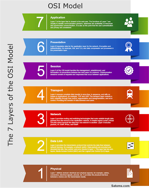
  What is the OSI Model? In telecommunications and IT networks, you will often hear people talking about the OSI model’s different layers. For example, a network engineer might refer to a router or switch as a Layer 3 device or a network technician talking about Layer 1 faults. The Open System Interconnection (OSI) model, created by ISO (International Standards Organisation), provides a standard framework and interoperability for IT networks and communication systems. Layers 1 to 4  are used to transfer data around a network, and 5 to 7 contain application-level data that the user interacts with at Layer 7. Each layer performs specific tasks before passing the flow of data to the adjacent Layers in the model. OSI Layers Layer 1  defines devices’ electrical and physical aspects, for example, cables, connectors, electrical signals, pinouts, etc. It provides the physical interface between a device and the transmission media. Layer 2  – The data link layer provides the t...

VSAT Link Terminology

Image
  VSAT terminology can often be confusing at first but it’s really quite simple and this diagram shows how it relates to the VSAT remote site or the Teleport hub side. The Uplink is always the link to the satellite and the downlink is always the link from the satellite irrespective of which side of the link you are, Teleport/Hub or VSAT remote site. Inbound and Outbound are often referred to as Inroute(s) and Outroute(s). The Outbound is from the teleport hub to the remote VSAT and the Inbound is the the remote VSAT to the teleport hub. Satellite VSAT Link Terminology