Basic Radio Awareness
Introduction to Radio Communications Principles
All forms of communication follow the same basic principles. In this first chapter, we explore those principles and the different ways in which people communicate. We also look at radio waves and learn how radio technology is able to make your voice heard many miles away.
WHAT IS COMMUNICATION?
Communication begins when somebody wants to convey information to somebody else. That information must be presented as some kind of pattern. For example, speech is a pattern, smoke signals are a pattern, talking drums are a pattern, telephone calls are pattern, Morse code is a pattern.
These patterns then travel over a communication channel, typically involving a medium. For instance, smoke passing through air, electrical signals passing through wire, or speech passing through the atmosphere as a series of pressure waves.
Once the pattern reaches the recipient, it needs to be decoded and it needs to be understood. Somebody needs to understand what the dots and dashes of Morse code mean or what the patterns of smoke signals mean, or simply to process the sounds that make up human speech.
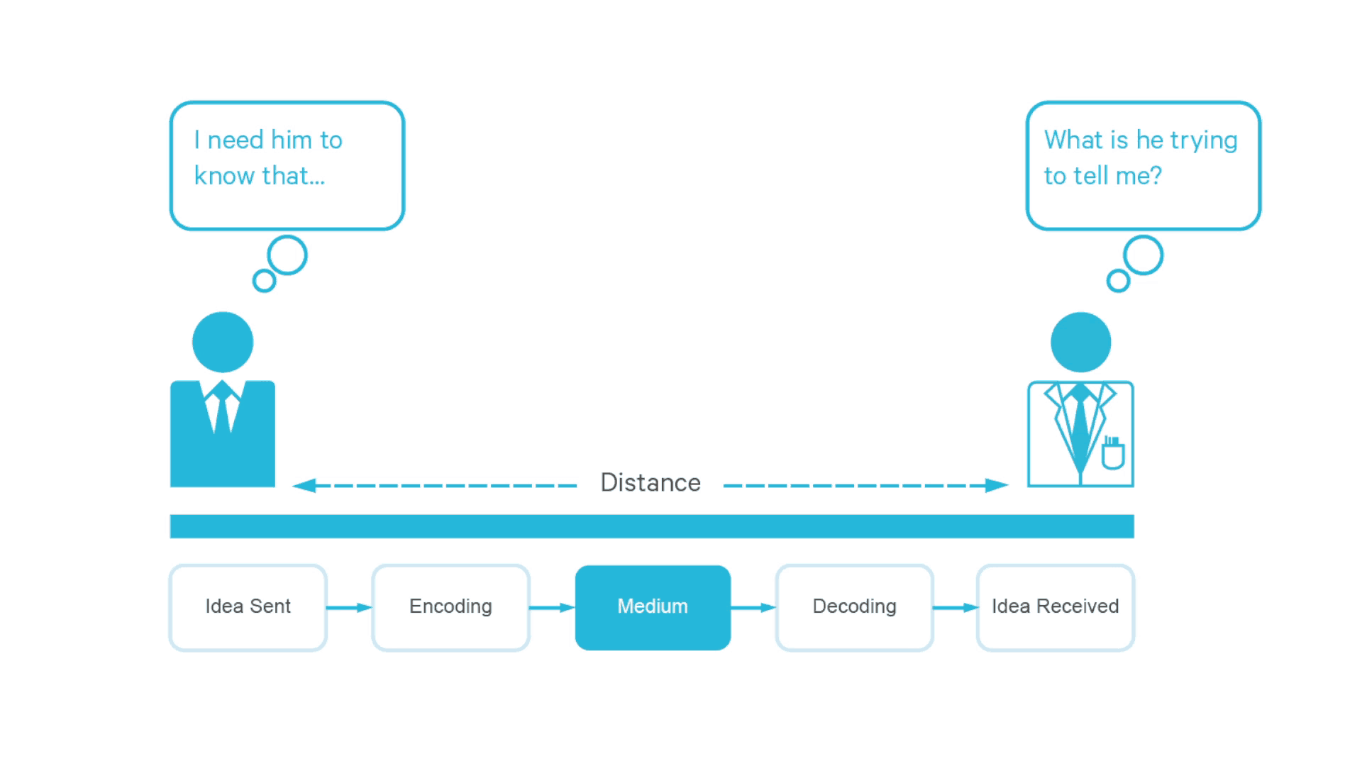
Lastly it’s received in a form in which the recipient can actually understand the information and act on it. That’s the basic model of all types of communication.
This is the way in which radio communication works. Somebody speaks into a radio, it gets encoded or turned into a pattern by the transmitter. It then gets sent as electromagnetic waves through a communication channel (the atmosphere), which is received by receiving a radio. It gets decoded so the pattern is understood, and it get converted again to sound that the receiver understands and can act on.
Introduction to Radio Communications Principles
WHAT IS A RADIO WAVE?
As mentioned in the basic communication model, in order to convey information to somebody:
- A user must impose a pattern,
- which interacts with a medium in a channel,
- which gets decoded at the recipient’s end,
- and is finally received in a form in which the recipient can understand it.
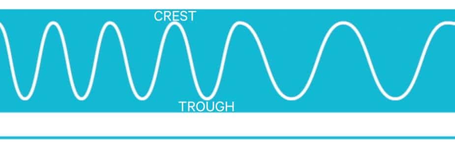
Most of these interactions between the patterns and the medium of the channel are best described by waves. When someone speaks, they’re using pressure waves in order to convey information to somebody else. These pressure waves represent points at which molecules of air are packed closer together, and points at which they’re further apart.
Energy is pumped into the atmosphere to compress molecules together. The high point of the energy which squashes the molecules closer together is called the crest of the wave. The low point of the energy, when the molecules are far apart, is called the trough of the wave.
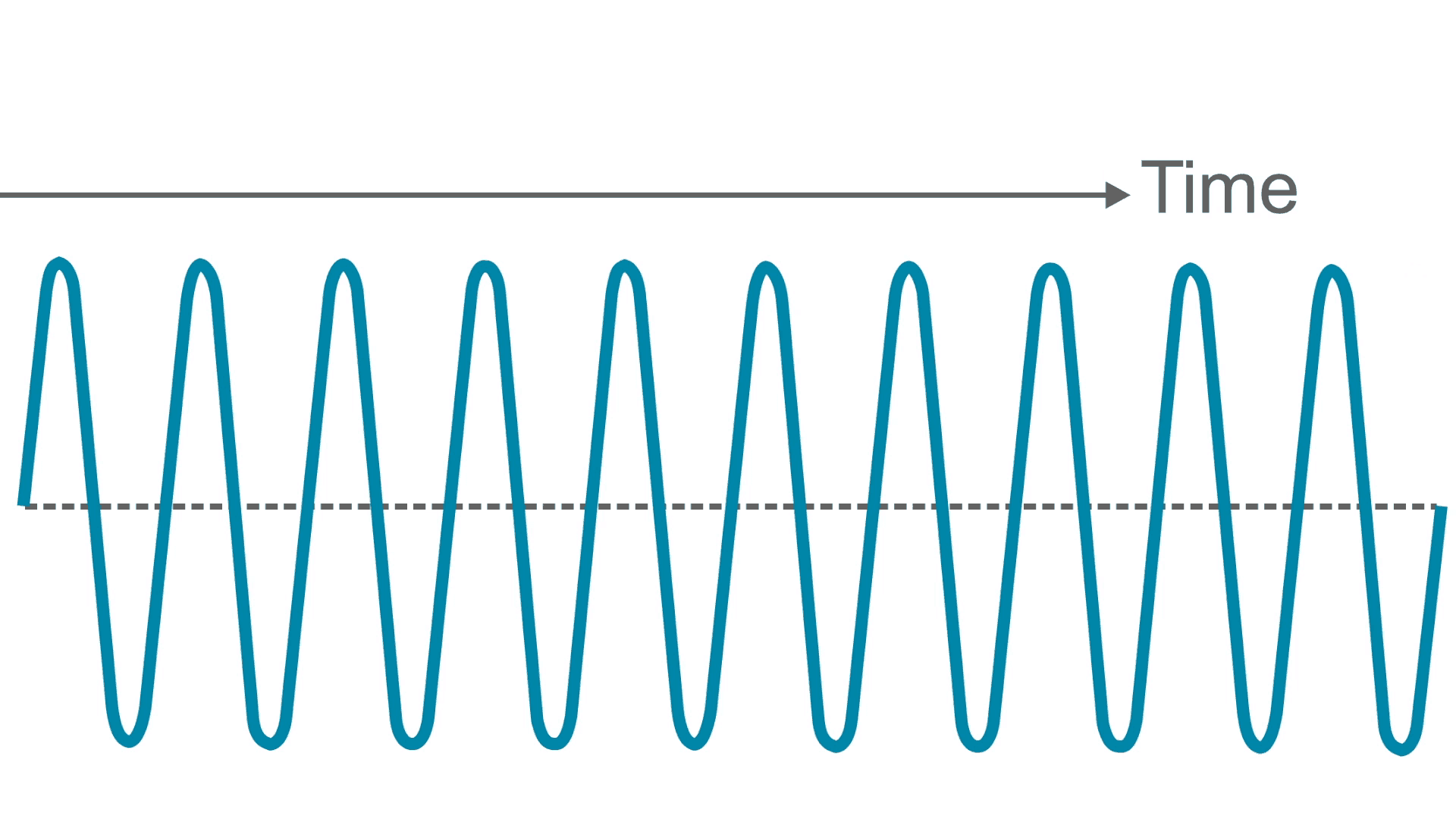
The number of waves passing by in a single second that would be the frequency. Frequency is simply the number of waves passing per second. Just like the ripples on a pond after a stone has been thrown into it, all the little ripples that passed through a certain point would indicate frequency. Radio frequency is identified as number of waves per second or cycles per second. The modern term for this is hertz.

Waves also have a wavelength to them – the distance between the same positions on two waves. In radio, wavelengths can be very long. A single wave can be the size of a human being.
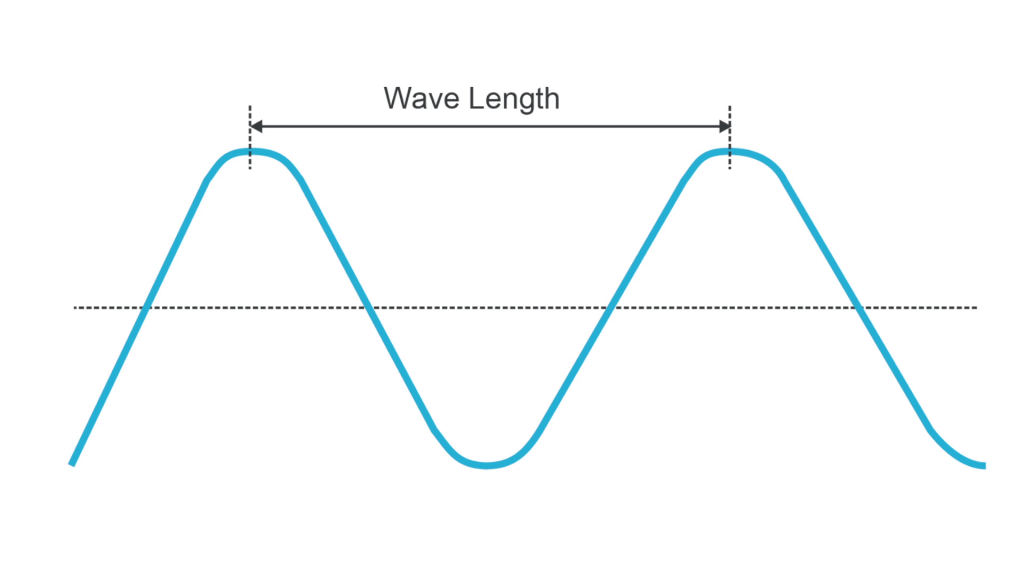
There are, however, much shorter wave lengths, which are shown on the electromagnetic spectrum, of which radio communications makes use of.
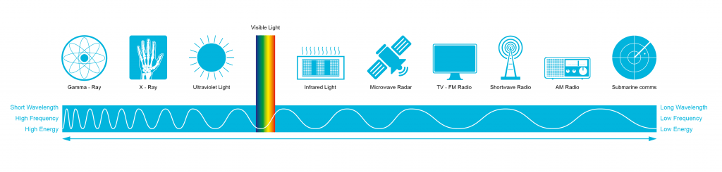
The electromagnetic spectrum stretches from gamma rays down to the lowest form of radio waves. They include the following:
- Gamma-Ray
- X-Ray (like in a medical examination)
- Ultraviolet light
- The optical spectrum that we can see: Red, orange, yellow, green, blue, purple.
- Infrared light
- Microwave Radar
- TV – FM Radio
- Shortwave Radio
- AM Radio
- Submarine communications
Humans are not the only users of the different parts of the electromagnetic spectrum. For instance, bees use ultraviolet and moths use infrared. In the radio part of the spectrum, however, humans are probably the only users.
Of the human usage of the radio spectrum, the biggest users are the military. They use the longest wave length radio in order to allow submarines to communicate with each other, and they also use the higher parts of the spectrum because it can penetrate buildings and communicate with people inside.
Introduction to Radio Communications Principles
WHAT IS PROPAGATION?
It’s useful when thinking about radio waves to think about light waves.
Light travels in rays, and radio waves do the same thing. It is called radio propagation. When white light goes into a prism it is separated by wavelength into red, orange, yellow, green, blue, and violet. In the same way, radio waves are going to propagate differently depending on their wave length. Radio wave lengths are much bigger than light wave lengths.
Look at propagation of radio rays traveling in order to communicate with users who are in different parts of the world, using (in radio terms) part of the VHF (Very High Frequency) spectrum. Radio that is in the VHF band travels in a straight line. In other words, the rays travel using line of sight.
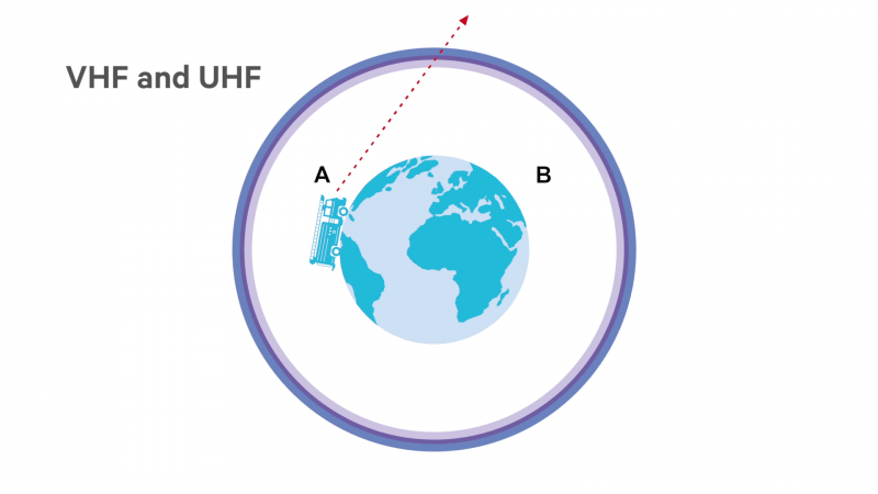
If two users on the opposite side of the world want to communicate, the radio wave cannot use line of sight propagation, because it travels in a straight line and will not go around the curve of the earth. So, the solution for contacting somebody who’s over the curved horizon is to put a satellite up, and the satellite will receive the signal from the radio caller, and then transmit it in another straight line, line of sight, to the person receiving it at the other end.
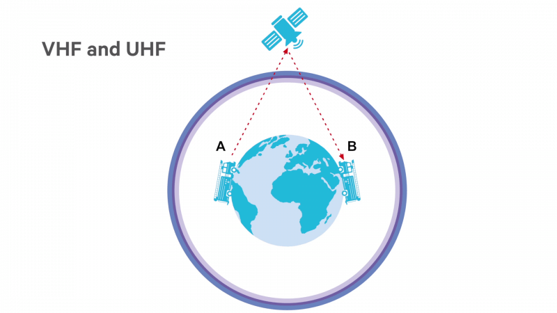
UHF (Ultra High Frequency) which, for example, would be 400 MHz, operates in exactly the same way. In longer wave lengths of radio, however, the propagation is different.
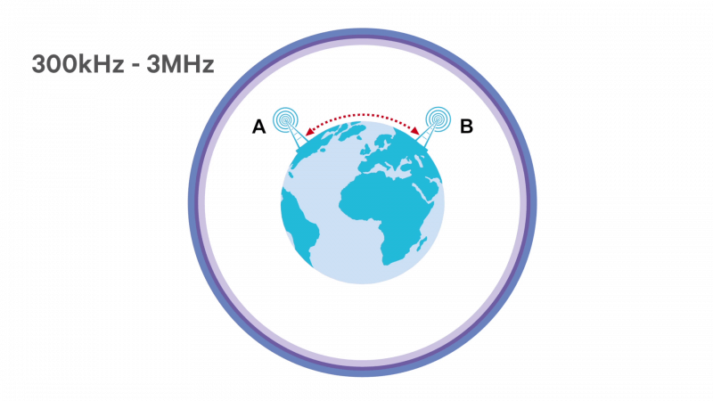
For example, in lower short wave, which is around 300 kHz to 3 MHz, the radio propagation or radio wave can actually curve itself around the horizon or the curvature of the Earth.
In higher short wave, which is what people in the 40s and 50s used to listen to when they wanted to hear international broadcasts, the properties are different again. The radio propagation is going to do an interesting exercise. First it bounces off a top layer of the atmosphere called the ionosphere, then it bounces back to the Earth (this is reflection. It then bounces up again to the ionosphere, and continues bouncing back again until it reaches the radio receiver. This is called a skywave, which works around 3 to 30 MHz.
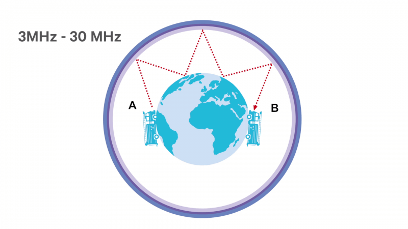
Radio propagation, like other radio properties, can depend critically on radio wavelength.
Introduction to Radio Communications Principles
HOW DO REPEATERS WORK?
Working with a handheld is similar to working with a walkie-talkie. As long as somebody is in a straight line from them, a user can talk to them. This is a radio to radio connection and is called simplex communication.
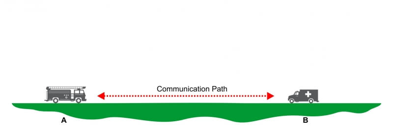
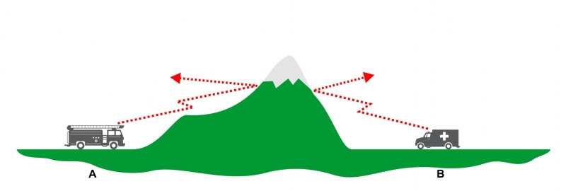
A walkie-talkie works fine if there is no obstruction between the radio that is calling and the radio that is receiving. But what happens if there is a hill or a big building in the way? Line of sight is no longer possible because something is blocking the radio.
Often in these situations, a radio that can repeat the message is placed on the top of the mountain, called a repeater (or base station). If a user wants to make a call on the handheld radio, the message goes in a straight line up to the repeater.
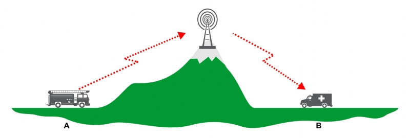
The repeater needs to receive the frequency that the caller transmitted with, and then the repeater re-transmits that same message down to the user on the other side of the mountain. It works similarly to the satellite discussed with VHF radio propagation, but instead of a satellite, it is a fixed radio on top of the hill.
Modulation and Radio Building Blocks
INTRODUCTION TO CHANNEL SPACING
Radio spectrum is very limited. Every user of radio spectrum needs a “pipeline” or block of pipelines in order to communicate over.
These pipelines are called channels and they are differentiated by their frequency. Just like a pipe has a certain diameter, an RF channel has frequency bandwidth or channel spacing.
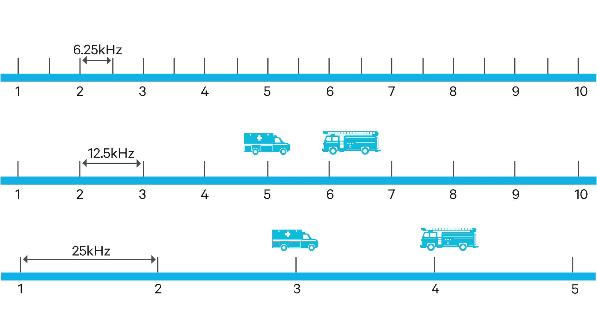
Wideband channels occupy 25 kilohertz of radio spectrum.
A narrowband channel is half that size and occupies 12.5 kilohertz
Ultra narrowband is half the size again at 6.25 kilohertz, and it is the smallest “pipe” of all.
There’s a basic engineering tradeoff here (engineering is full of tradeoffs). The smaller the channel spacing is, the greater the number of channels that can fit into a given block of radio spectrum. More channels mean that more users are able to use the available spectrum to communicate. However, the wider the channel spacing is; the better the reception and audio fidelity will be. So there’s a tradeoff here between audio fidelity and reception on the one hand, and getting the maximum use of the radio spectrum on the other.
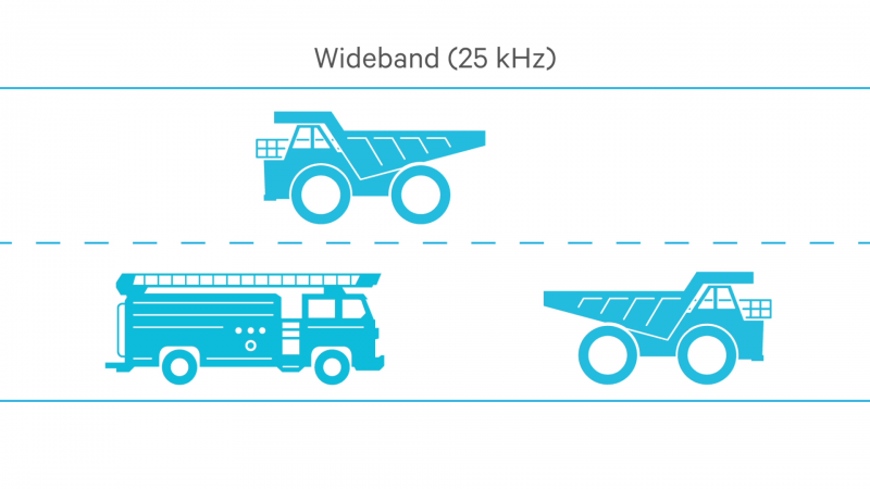
A block of radio spectrum is like a big section of highway, a fixed width across. It’s got to support two lanes: One for receiving radio, one for transmitting radio. A wideband channel is like having two big lanes, big enough to transport a house down each lane. This is like wideband, and it is not a very efficient use of this highway; a more efficient use would be if these big single lanes were sub-divided into half-sized lanes.
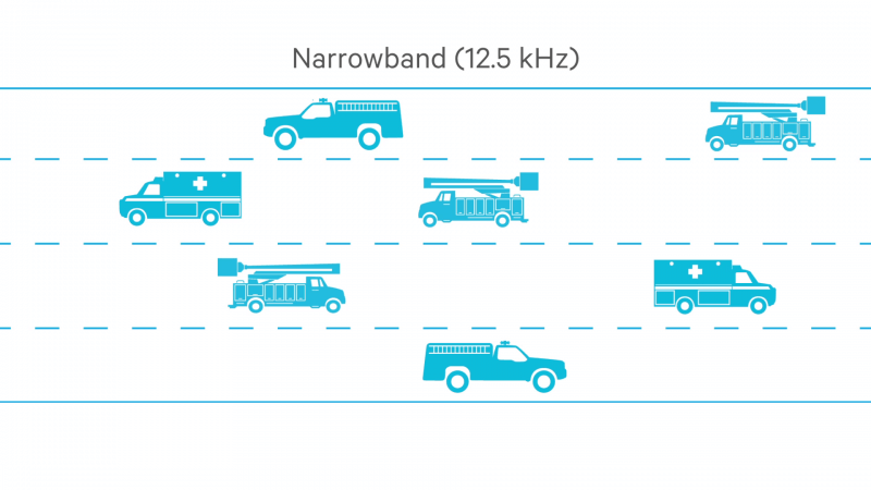
With these half-sized lanes, houses cannot be transported through anymore, but trailers and SUVs can probably fit through without any trouble. The number of users has increased, but those big chunks like the houses can no longer fit through. This is similar to how Narrowband works.
Modulation and Radio Building Blocks
In this chapter we discuss modulation and the building blocks of radio. How does your voice get converted into waves that can be transmitted and received by radio devices?
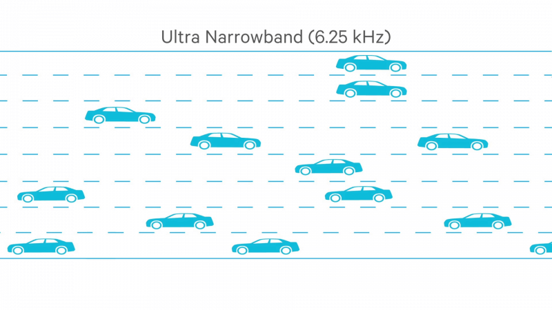
To get even more users, sub-divide these two half-sized lanes into a four lane highway on each side: Four lanes receiving and four lanes transmitting. Now only quite small cars will fit through. More users can get through, but a part of the functionality has been lost. This is similar to how Ultra Narrowband works.
Modulation and Radio Building Blocks
HOW DOES AN FM TRANSCEIVER WORK?
Take a look at this FM transmitter diagram:
![]()
The process is relatively straightforward:
1) The microphone takes the voice in.
2) This voice signal goes into an audio processor in order to create an input signal.
3) The input signal is combined with a carrier frequency that is generated by the voltage controlled oscillator (V.C.O.).
4) The result is a signal that carries our information but is not sufficiently powerful enough to be transmitted up through an antenna. The signal is amplified through two different stages:
5) The exciter stage amplifies the signal power up one level of output.
6) The power amplifier drives it up to another power output level, now sufficient for the transmitter’s antenna.
The receive process is very similar:
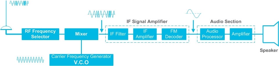
1) The transmission is captured by the receiver antenna and fed into an RF frequency selector.
2) The transmission goes into a mixer where it’s combined with a carrier generated by a local V.C.O.
3) The result is then fed into an IF (Intermediate Frequency) signal amplifier. It reduces the frequency through a filtering process that’s required to strip out the carrier more easily.
4) The signal is demodulated.
5) The result is fed into an audio section which amplifies the results so that it can be fed into a speaker and heard by the user.
An FM transceiver simply combines an FM transmitter and an FM receiver in a single unit. The r
Modulation and Radio Building Blocks
THE DIFFERENCE BETWEEN FDMA AND TDMA
An RF channel occupies a certain amount of radio spectrum. What is the most efficient use of this small chunk of radio spectrum that makes up our channel?
There are two different techniques.
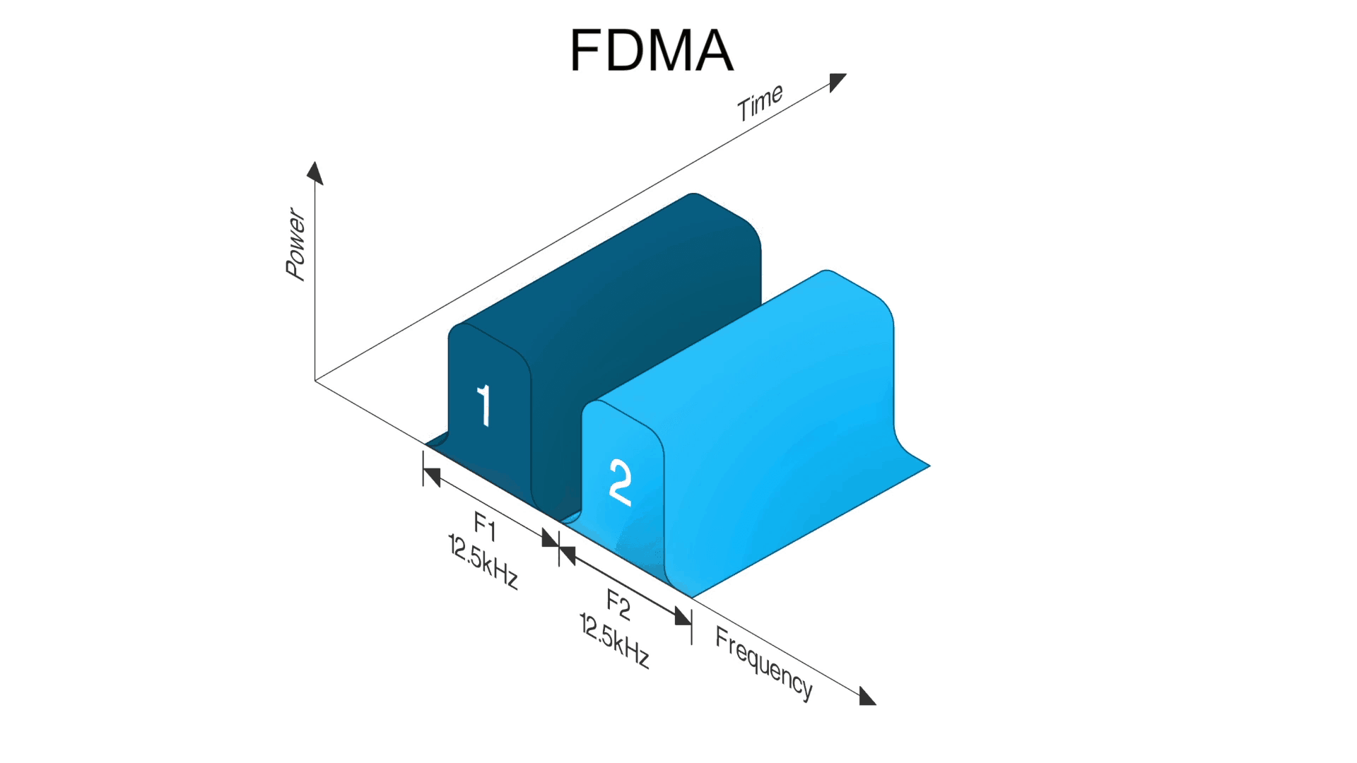
The first technique is called frequency division multiple access (FDMA). This method separates channels by frequency, so if users want to have two channels they’ll have two separate frequencies. If a conversation runs across a channel, it occupies the whole of the channel exclusively. There is only one conversation and one user at a time per radio channel. More radio channels require more frequencies.
There is an alternative technique: Time division multiple access (TDMA).
TDMA occupies a channel but it allows two users to occupy the same channel at what appears to them to be the same time. An analogy could be the still shot frame rates in cinema, where at around 30 frames per second it gives the illusion of continuous movement but it is actually a time shuttling exercise.
With a 2-time slot TDMA system, two users can share the same frequency in the following manner: User 1 gets to use the frequency for a very short fixed period of time, perhaps 50 milliseconds. Then the channel reverts to user 2 who gets 50 milliseconds. Then it cycles again back to user one who gets a further 50 milliseconds, and so on and so forth.
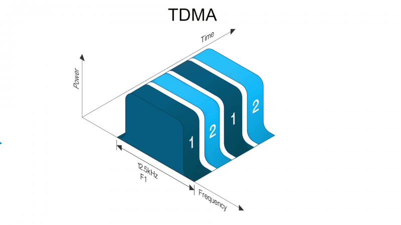
This process is so fast that each user thinks they have exclusive use of the frequency channel. With 2-time slot TDMA, in order to have more than two conversations going on at the same time then another radio channel is needed. If it is another 2-time slot TDMA channel then two frequencies can simultaneously support four conversations; or apparently simultaneously, because of this shuttling exercise.
Receiver section of the transceiver is the same as what is seen in the FM receiver section and similarly for the FM transmitter.
Modulation and Radio Building Blocks
THE CORRELATION BETWEEN RANGE AND POWER
Range and power of portable and mobile radios have an interesting relationship.
With both portables and mobiles, the radio converts radio power into radio frequency power and is radiated out of the antenna. Range of a radio is dependent on both the power that’s available to it and also the frequency in which it’s working.
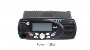
A mobile radio, which has between 25 and 50 watts of output power, is hooked up to the mains or to a car battery and is a pretty substantial radio. Because of the high output power, it will have high range. Additionally, a mobile radio radiates a lot of power, and therefore also radiates a lot of heat. This is why mobiles have a metal body; to drain off the excess heat.
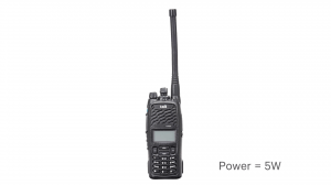
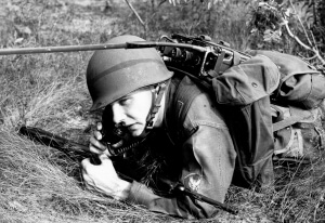
By contrast, a portable radio only has an output power of about 5 watts. Because it uses a smaller battery and does not radiate so much heat, it does not need a metal body. A plastic body will suffice, and for convenience’s sake, portables have a smaller antenna. It could have a larger one to radiate out further, but this would stick like a car antenna from somebody’s back pocket or hip. This can be seen with Army personnel or police in foreign countries.
The mobile has greater range than the portable simply because it has more power available to it.
Frequency also has a part to play in this relationship. The range available in some frequencies is better than others. For instance, VHF travels further than higher frequencies such as UHF, or 700 and 800 megahertz. On the flip side, higher frequencies actually travel inside buildings better.
In conclusion, the range depends very much on both frequency output power.
Communications Systems
No two communication networks are the same. Trunked or conventional? Digital or analog? TDMA or FDMA? In chapter three, we explore the different types of communication systems and their various benefits and disadvantages.
- How do repeater systems work?
- How Scanning Works
- Voting and Simulcast networks
- Digital vs. Analog
- Different types of radio
- How does trunking work?
Communications Systems
HOW DO REPEATER SYSTEMS WORK?
As previously discussed, repeaters help with the problem of line of sight in conventional communications. If two radios want to communicate with a hilltop in the way, then there is no line of sight. One way to overcome this is placing a repeater (or base station) at the top of the hill. One radio communicates up to the repeater, this is called uplink, and then the repeater repeats that transmission down to the radio on the other side of the hill, this is called downlink.
However, repeaters are used even when there are no hills in the way as they are excellent for extending range. A repeater is an extremely powerful radio. Portable radios work in five watts, mobile radios work in 25 watts or more, and repeaters are even more powerful radios in the 50 to 100 watt range.
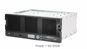
Repeaters are generally in fixed positions at particular geographical locations. This can sometimes be in their own special hut or in some type of enclosure. They have a cable connection to antenna systems, which are either mounted on steel towers or simply fixed to the top of the building.
Mobile radios and portables can take advantage of the greater power available in the larger size of the antennas. A collection of repeaters connected together provide mobile portable radio users coverage over an extremely wide area, thus extending the range of communications.

HOW SCANNING WORKS
Portable and mobile users are constantly on the move. When they work on a system with multiple repeaters in different locations, it can be difficult for the different units to keep in touch. One method is for each user to check the different channels by hand to see if there is any communication activity on the channel. An obvious problem here is that one may miss a call by being on the wrong channel at the wrong time.
A better way of doing this is a process called scanning. This enables the radio to automatically check each channel in turn, one after the other to see if there is any activity going on. If activity occurs, the radio will lock on to that channel and then send the audio to the speaker so that the radio user can hear it.
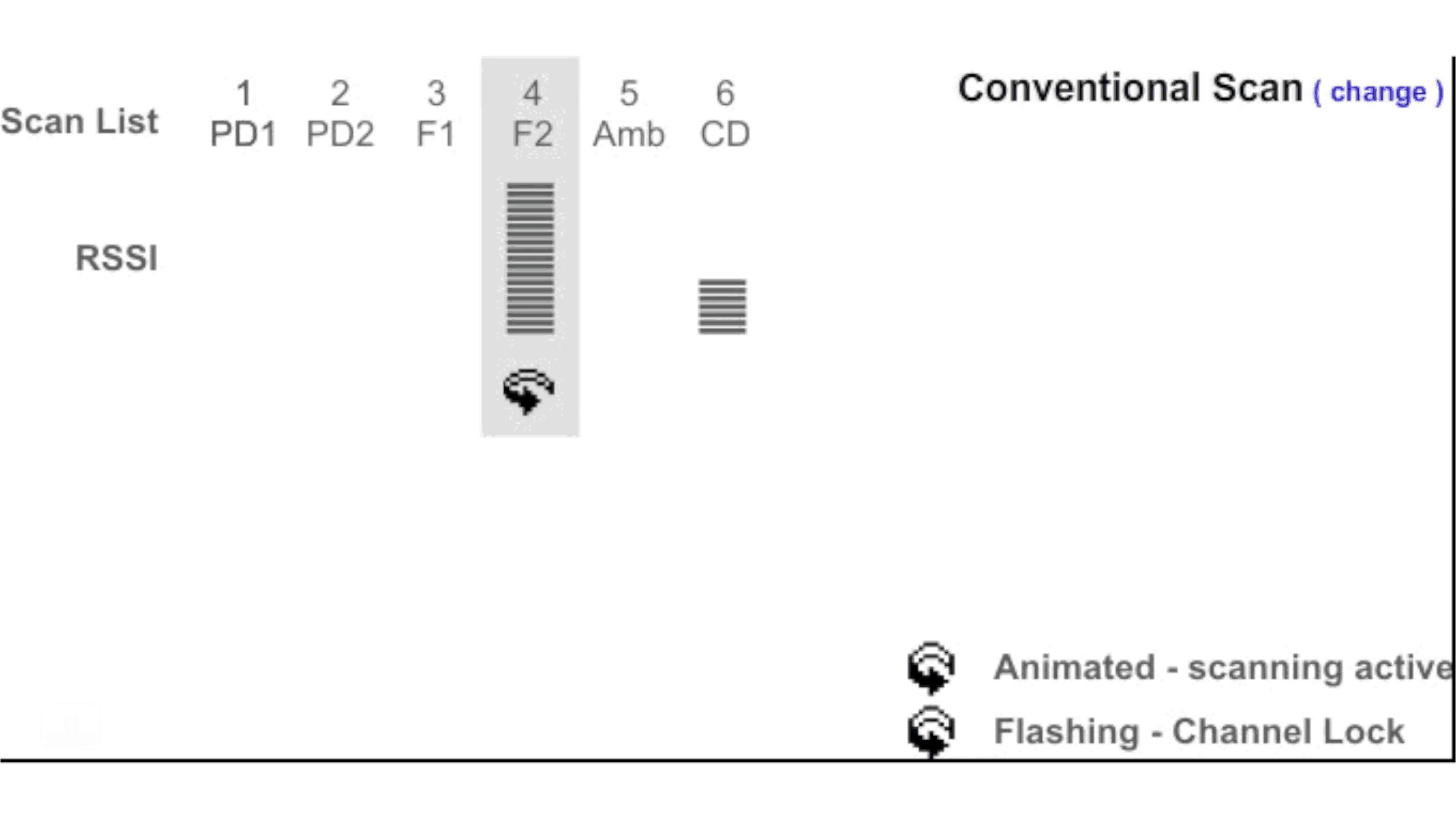
Scanning also allows users to monitor other channels for activity while talking on one. The group of available channels to scan through is called a scan group.
When a radio locks on to a channel during the scanning process, it is called capturing a channel. Scanning can be used for talking as well as listening, and there are several different ways to program the scanning capabilities.
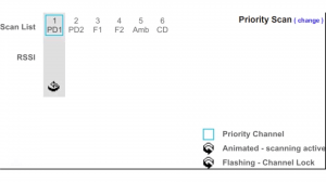
A radio can be programmed to allow a user to press the PTT and then talk on the captured channel. Alternatively, it can be configured to return the user to a default channel for transmissions. Priority scanning can be configured on a radio to allow important channels to be scanned more frequently in order to capture important traffic ahead of time.
VOTING AND SIMULCAST NETWORKS
Suppose a system has a number of different repeaters at different sites. All are transmitting the same audio, but users are often on the move. While they may begin with excellent reception at the first site, eventually they will experience better reception at the second site than the original first site.
A process called voting ensures that generally the radio user will get the best possible reception. Voting can occur in the subscriber units (downlink voting) or in the network (uplink voting) or in a combination of both.
Downlink voting, which takes place in the subscriber unit, allows the radio to automatically select the best quality channel from a group of channels that are transmitting the same audio.
This takes places in three stages:
Stage 1. The radio searches for activity on the channel in a process similar to scanning.
Stage 2. The subscriber unit measures the signal quality of all the channels.
Stage 3. The subscriber unit goes to the channel with the best signal strength and unmutes the receiver. In the background the scanning process continues to take place.
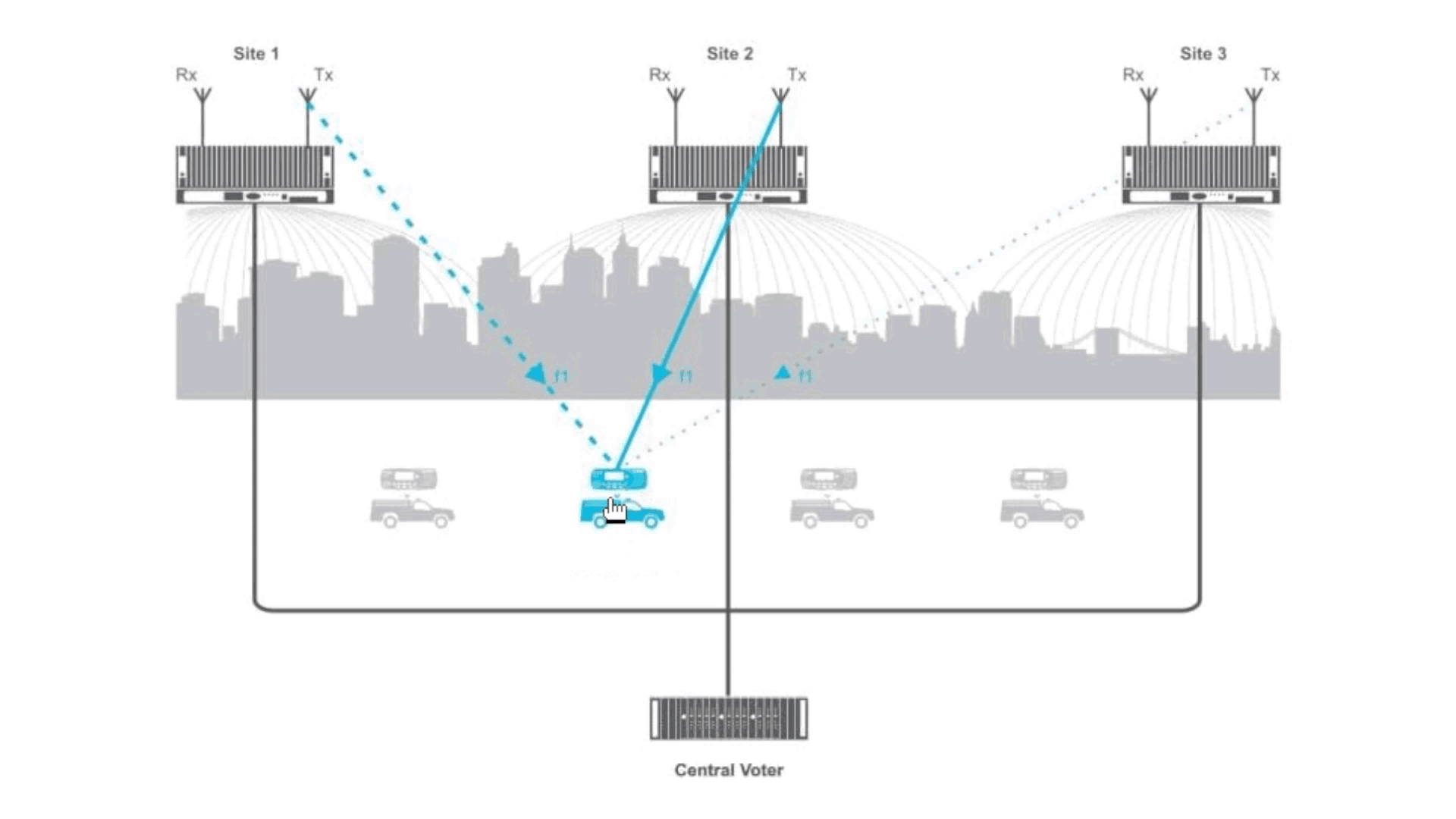
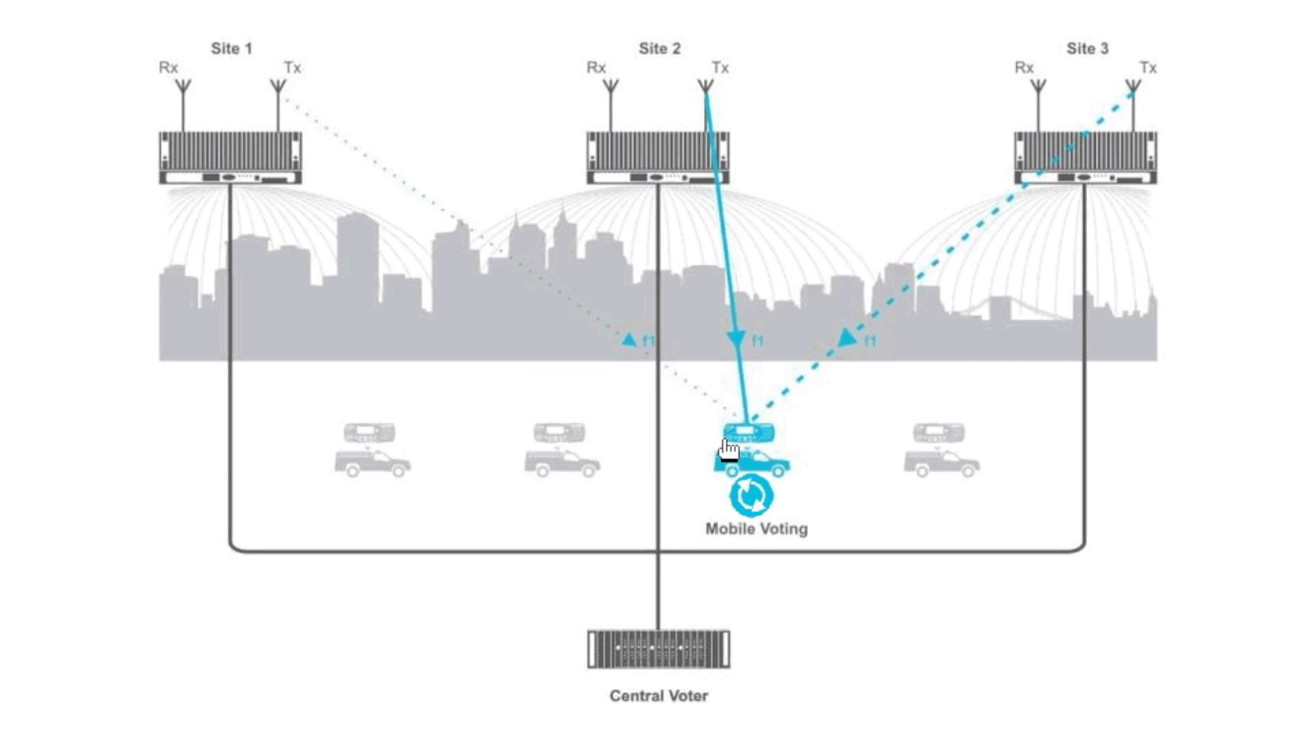
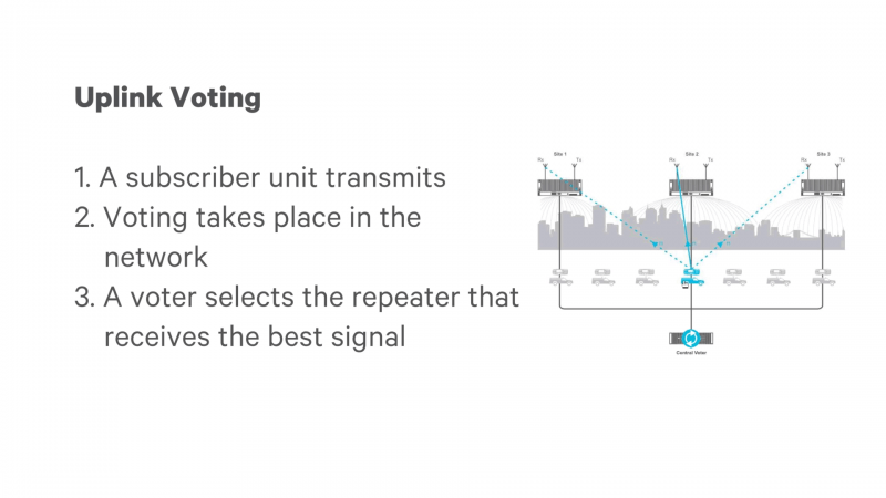
Uplink voting takes place in the network. It usually involves a network that has repeaters receiving on the same frequency, but transmitting at different frequencies. The network selects the best signal for repeating throughout. A subscriber unit transmits and voting then takes place in the network. A special box, such as a voter, selects the best possible audio from amongst the received signals because all the repeaters are receiving that transmission from the SEU. Such a network is called a voting network.
Another kind of voting network is called a simulcast network. It involves transmitting the same audio using the same modulation on the same frequency with multiple transmitters, all transmitting at exactly the same time. A simulcast network is designed so that all the repeaters synchronize their transmissions in time, making them appear as an extremely large single super repeater with a super large coverage area. This coordination of transmission is quite challenging, but for users operating a simulcast network it produces a great result.
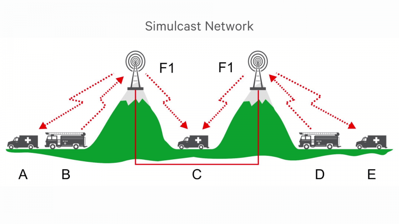
The radios can move from one location to another without the user touching the radio or modifying its settings or changing channels, because they operate on a single frequency. The radios work everywhere.
DIGITAL VS. ANALOG
The radio technologies previously mentioned are all open standards, which means that equipment from different manufacturers can work together. Digital radio, however, does offer some particular advantages over analog.
Security: One of the most important advantages is security. With digital, encryption can be used without degrading the quality of the audio or the range at which the radio works.
Data: Digital radio technologies make use of IP-based networks. This means that the data capabilities are increasingly flexible.
Spectral efficiency: Digital makes better use of channels than analog, so the utilization, or spectral efficiency, of digital systems tends to be greater than for analog systems.
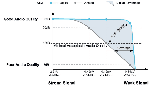
Clear audio: There is also a better opportunity for reducing background noise in digital, because we can screen the noise and interference out more effectively. This occurs all the way to the edge of coverage – giving clearer audio than analog at greater distances.
These are some powerful advantages of the modern digital standards that have emerged over the last few decades.
DIFFERENT TYPES OF RADIO
We have now covered Conventional, Trunking, and Simulcast systems. Next we’ll cover the different radio technologies that actually support these different types of operation.
Conventional FM: As previously mentioned, conventional FM is a popular technology in analog radio. Almost every major manufacturer in the world supports some form of conventional FM technology.
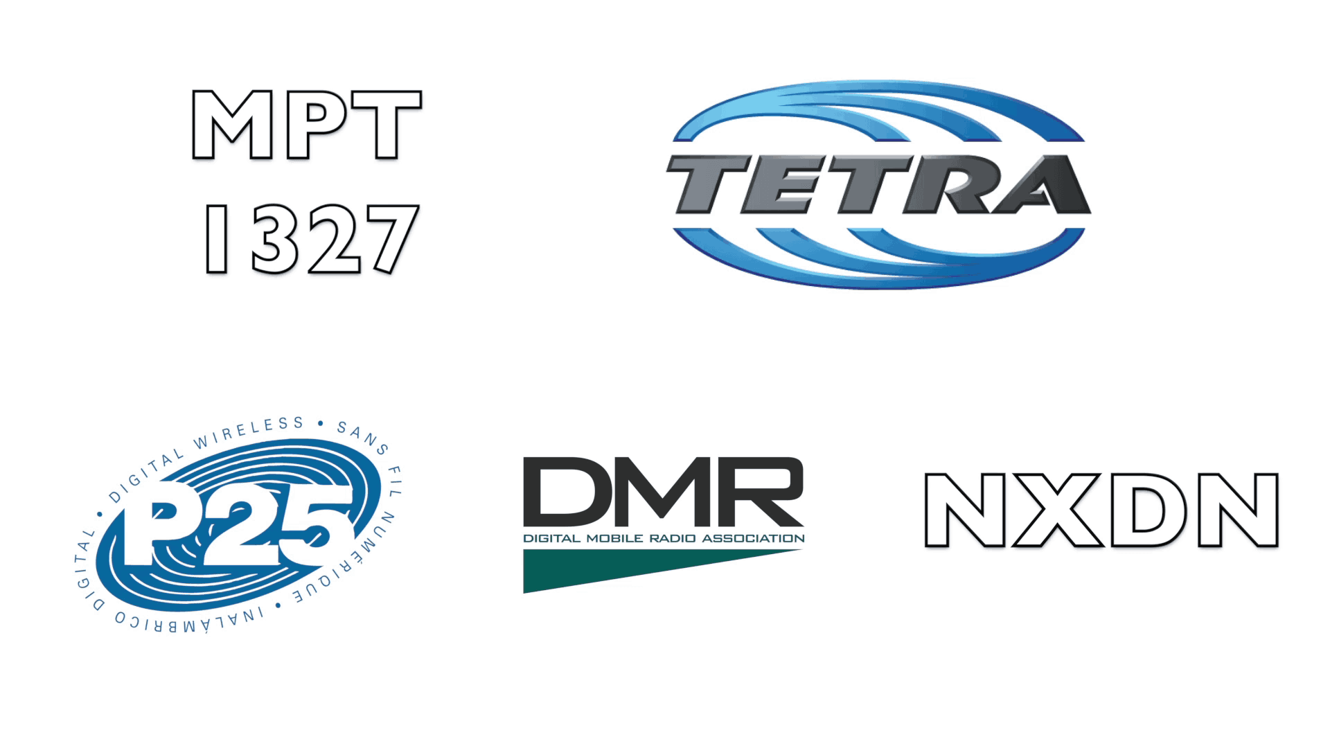
MPT1327: Perhaps the most widely used analog trunking technology today is called MPT 1327. It is named after the UK Ministry of Post and Telegraph that invented this particular open standard. A number of different manufacturers support this trunking technology.
Tetra: As the world becomes more digital, a number of digital radio technologies have emerged. One of these is Tetra, developed in Europe in the late eighties. It’s very similar to GSM used in modern digital cellphones. Tetra is a 4-slot TDMA technology that works in 25 kHz (wideband) channel spacing. It’s very popular amongst large public safety agencies and used in the airports and has strong data applications. Tetra operates in specific bands: 380 to 420 MHz and in the 700/800 MHz system.
P25: Another major open standard for digital radio technology is APCO Project 25 or P25 for short which was developed specifically for public safety agencies in the United States. P25 Phase 1 differs from Tetra by being an FDMA technology and also supporting conventional, trunked, and simulcast operation (or a combination of all three of these).
P25 can be used in any licensed frequency that a public safety agency has whether it be VHF, UHF, 700, 800, even 900 MHz. It can be employed by non-public safety users as well. P25 actually comes in two phases. Phase 1 is an FDMA technology operating in the 12.5 kHz channel spacing. Phase 2 is a more recent development and is only available in trunked. It is also TDMA and offers two time slots in a single 12.5 kHz channel spacing given the equivalent of a 6.25 kHz channel.
DMR: One of the newest open radio standards is called digital mobile radio or DMR for short. It’s a TDMA technology which uses 2-time slots and operates in the 12.5 kHz channel spacing, available in any licensed frequency. Tier 2 DMR offers conventional operation and Tier 3 DMR offers trunked operation. DMR is increasingly used by businesses such as mining, utilities and transport throughout the world.
NXDN: NXDN is a FDMA technology, similar to DMR, which operates in a 6.25 kHz channel spacing. It’s not limited to any particular frequency band and it also supports conventional and trunked operation.
HOW DOES TRUNKING WORK?
Trunked networks get their name from the world of telephony. Traditionally two cities would bundle their connections together into a single thick line like the trunk of a tree, which is known as a trunked line. The local household loop lines operated like the branches of a tree, one line for each household.
The reason why trunking has become so important is because it offers some huge advantages over conventional for larger agencies.
A conventional system is a system that has dedicated channels, allocated to a specific user or a group of users. Channel one might be fire, channel two might be fire chiefs, channel three might be animal control. If you want to communicate with a particular group in conventional, then you need to manually select a channel by hand either by moving a selection knob on the radio or by using a drop down menu.
Conventional has some huge advantages and is still popular around the world today. It’s very fast to set up a call, it’s easy to use and it’s pretty inexpensive. However there are some downsides as well. Remember conventional means using dedicated channels that are manually selected. When a channel is being used, it’s used exclusively by one caller, so anybody else who wants to make a call on that channel has to wait until the call is over. It causes an inefficient use of radio channels. Channel one (the fire channel), would probably be frequently busy. On the other hand, channel three (the animal control channel), can go idle as it probably would not be as frequently used.
So while callers may be waiting to use channel one, they cannot make use of channel three even though it’s completely idle. If a user wanted to add call groups, they would need to add a new selectable channel. In this sense, users are limited by how many channels they can select manually. It also adds the headache of reprogramming all the radios anytime a new channel or user group is added.
For small agencies, a conventional system is absolutely perfect. If they know the groups that will communicate together, a conventional system is a good choice. But as soon as the number of groups or the number of users working on a system increases, trunking may be a better option.
Trunked radio might be better called “computer-controlled” or “computer-aided” radio. When a trunked radio user wishes to communicate with another user or group, the computer automatically assigns them the first free available channel to make each call. The underlying principle of trunking is that not all users or groups who need to communicate in a channel will do so at the same time. Therefore there can be many more users or groups than there are channels in the system.
A good way to explain Trunking to use the following analogy: Consider a conventional bank in which specific tellers are dedicated to specific types of customers. For example, one teller focuses on cash withdrawals, another on cash deposits, and another only on business accounts.
So what happens at lunch time? A long queue develops as household users want to make cash withdrawals or put in cash deposits and that teller gets overloaded. The business teller, however, helps one or two business customers spends most of lunch time idle. This is the problem with conventional systems.
By contrast, a Trunking teller can serve any type of customer and do any sort of transaction. So at lunch time when the long queue of household users wanting to make cash withdrawals or cash deposits is mixed in with the business users, a controller at the head of the queue simply assigns each customer to the first available teller.
This means more transactions can occur because the tellers are far more flexible and the trunking controller at the head of the queue is an intelligent intermediary who can direct traffic and maximize efficiency.
So that’s the basic difference between conventional and Trunking networks: In conventional the users manually control the allocation of channels by selecting from a knob, whereas in Trunking systems, a computer at the center of the network is responsible for channel selection.
No two communication networks are the same. Trunked or conventional? Digital or analog? TDMA or FDMA? In chapter three, we explore the different types of communication systems and their various benefits and disadvantages.


Comments
Post a Comment