FIBRE OPTICS TRAINING
Fibre Optics Course Introduction
![]()
Welcome to the Fibre Optics Training Course. We have put together a comprehensive course that covers all aspects for the Fibre Optic technicians and users. We hope you are confident with the essential operation, termination, maintenance, and fault finding of Fibre Optics cables and equipment by the end of the course.
These are a few tips to help you during the course:
- Take your time during the lessons
- Take notes
- Go back and re-read the lesson if needed
- If you don’t understand email support
- Download the PDF help sheets, manuals, spec sheets, and course notes for reference
- Download any recommended software
The training course does not have to be completed at once, you can log off at any time, and your course progress will be saved. When you next log back in, the course will resume from the lesson you reached previously. The lessons contain video, text, and other learning material. You should view all content before making the lesson complete.
Email support@satoms.com if you have any questions during the course, and please remember to leave a course review when you have completed to course.

Click the ‘Complete’ button below at the end of a lesson to mark that lesson as completed in your user dashboard.
Basic Principles of Fibre Optics

An optical fiber is a flexible, transparent fiber made by drawing glass (silica) or plastic to a slightly thicker diameter than a human hair. Optical fibers are used most often as a means to transmit light between the two ends of the fiber and find wide usage in fiber-optic communications, where they permit transmission over longer distances and at higher bandwidths (data rates) than traditional copper cables like structured cabling (CAT 5e, 6 and 7).
Fibers are used instead of metal wires because signals travel with less loss. Fibers are also immune to electromagnetic interference, a problem from which metal wires suffer excessively. Fibers are also used for illumination and imaging and are often wrapped in bundles so they may be used to carry light into or images out of confined spaces, as in the case of a fibrescope. Specially designed fibers are also used for other applications: fiber optic sensors and fiber lasers.
Optical fibers typically include a core surrounded by a transparent cladding material with a lower index of refraction. Light is kept in the core by the phenomenon of total internal reflection, which causes the fiber to act as a waveguide. Fibers that support many propagation paths or transverse modes are called multi-mode fibers (MMF), while those that support a single mode are called single-mode fibers (SMF).
Multi-mode fibers generally have a wider core diameter and are used for short-distance communication links and applications where high power must be transmitted.
Single-mode fibers are used for most communication links longer than 1,000 meters (3,300 ft).

Fibre also offers higher bandwidth compared to copper cabling. It can be used in voice, video, and data applications are commonly seen with IP surveillance cameras and NVRs located throughout a facility. The cost of fiber continues to decline as many manufacturers can now produce high-quality fiber cabling, connectors, and transceivers.
The use of fiber optic technology in harsh environment communications systems provides several benefits. The first is that fiber is immune to EMI and RFI “noise,” commonly encountered on a manufacturing floor or processing plant. Secondly, fiber can support very long distances before a repeater is necessary, covering thousands of kilometers.
Elements of a Fibre Link
What is Fibre Communication?
It is the transmission of information as a modulated beam of light by;
- Semiconductor technology, which produces the necessary light sources and detectors.
- The guidance of light within an optical fiber.
Fundamental Elements of a Fiber Optic Link

Elements of a Fiber Optic Link
- Light Source – Maybe an LED (Light Emitting Diode), either an Edge emitting or a Surface-emitting LED or LASER (Light Amplification by Stimulated Emission of Radiation), which there are several types.
- Detectors – Maybe one of several types, e.g., PIN Diode, APD (Avalanche Photo Diode), or an IDP, an Integrated Detector Pre-amplifier (PINFET).
- Optical Fibre – May be Multi-mode or Single-mode fiber.
- Connectors – In optical fiber terms, a connector is a device that connects 2 optical elements, i.e., fiber to fiber, the light source to the fiber, or detector to fiber.
- Couplers – A device that connects 3 or more optical elements, necessary in multi-access links, e.g., a LAN
- Pigtails – Small lengths of fiber connected directly to the source and detector to facilitate the connection of these components to the fiber link.
Fibre Optic Terms
You are not expected to know every abbreviation in this list, but it would be handy to know most of these terms commonly used in Fibre Optics.
You can download the PDF at the bottom of this page.
A
Absorption: That portion of fiber optic attenuation resulting in the conversion of optical power to heat.
Analog: Signals that are continually changing, as opposed to being digitally encoded.
Attenuation Coefficient: Characteristic of the attenuation of an optical fiber per unit length, in dB/km.
Attenuation: The reduction in optical power as it passes along a fiber, usually expressed in decibels (dB). See optical loss.
Attenuator: A device that reduces signal power in a fiber optic link by inducing loss.
Average Power: The average over time of a modulated signal.
B
Back Reflection or Optical Return Loss: Light reflected from the cleaved or polished end of a fiber caused by the difference of refractive indices of air and glass. Typically 4% of the incident light. Expressed in dB relative to incident power.
Backscattering: The scattering of light in a fiber back toward the source, used to make OTDR measurements. Bandwidth: The range of signal frequencies or bit rate within which a fiber optic component, link, or network will operate.
Bending loss or Micro bending Loss: Loss in fiber caused by stress on the fiber bent around a restrictive radius. Bit-error rate (BER): The fraction of data bits transmitted that are received in error.
Bit: An electrical or optical pulse that carries information.
Buffer: A protective coating applied directly to the fiber.
C
Cable: One or more fibers enclosed in protective coverings and strength members.
Cable Plant or Fibre Optic: The combination of fiber optic cable sections, connectors, and splices forming the optical path between terminal devices.
CATV: An abbreviation for Community Antenna Television or cable TV.
Cladding: The lower refractive index optical coating over the fiber’s core that “traps” light into the core. Connector: A device that provides a demountable connection between two fibers or a fiber and an active device and provides protection for the fiber.
Core: The center of the optical fiber through which light is transmitted.
Coupler: An optical device that splits or combines light from more than one fiber.
Cutback Method: A technique for measuring the loss of bare fiber by measuring the optical power transmitted through a long length, then cutting back to the source and measuring the initial coupled power.
Cutoff Wavelength: The wavelength beyond which single-mode (SM) fiber only supports one mode of propagation.
D
dBm: Optical power referenced to 1 milliwatt.
Decibel (dB): A unit of optical power measurement that indicates relative power on a logarithmic scale, sometimes called dBr. dB=10 log ( power ratio)
Detector: A photodiode that converts optical signals to electrical signals.
Digital: Signals encoded into discrete bits.
Dispersion: The temporal spreading of a pulse in an optical waveguide. Modal or chromatic effects may cause it.
E
Edge-Emitting Diode (E-LED): A LED emits from the edge of the semiconductor chip, producing higher power and narrower spectral width.
End finish: The quality of the end surface of a fiber prepared for splicing or terminated in a connector.
Excess Loss: The amount of light lost in a coupler, beyond that inherent in splitting multiple output fibers.
F
Fibre Amplifier: an all-optical amplifier using erbium or other doped fibers and pump lasers to increase the signal output power without electronic conversion.
Fibre Distributed Data Interface or FDDI: 100 Mb/s ring architecture data network.
Ferrule: A precision tube that holds a fiber for alignment for interconnection or termination. A ferrule may be part of a connector or mechanical splice.
Fibre Tracer: An instrument that couples visible light into the fiber allows visual checking of continuity and tracing for correct connections.
Fibre Identifier: A device that clamps onto a fiber and couples light from the fiber by bending to identify the fiber and detect high-speed traffic of an operating link or a 2 kHz tone injected by a test source.
Fiber optics: Light transmission through flexible transmissive fibers for communications or lighting.
FO: Common abbreviation for “fiber optic.”
Fresnel Reflection or Back Reflection or Optical Return Loss: Light reflected from the cleaved or polished end of a fiber caused by the difference of refractive indices of air and glass. Typically 4% of the incident light.
Fusion Splicer: An instrument splices fibers by fusing or welding them, typically by an electrical arc.
G
Graded Index (GI): A type of multimode (MM) fiber that used a graded profile of refractive index in the core material to correct dispersion.
I
Index of Refraction: A measure of the speed of light in a material.
Index Matching Fluid: A liquid used of a refractive index similar to the glass used to match the materials at the ends of two fibers to reduce loss and back reflection.
Index Profile: The refractive index of a fiber as a function of the cross-section.
Insertion Loss: The loss caused by inserting a component such as a splice or a connector in an optical fiber.
J
Jacket: The protective outer coating of the cable.
Jumper Cable: A short single fiber cable with connectors on both ends used for interconnecting other cables or testing.
L
Laser Diode (ILD): A semiconductor device emits high-powered, coherent light when stimulated by an electrical current. Used in transmitters for single-mode fiber links.
Launch Cable: A known good fiber optic jumper cable attached to a source and calibrated for output power used as a reference cable for loss testing. This cable must be made of fiber and connectors of a matching type to the cables to be tested.
Light Emitting Diode (LED): A semiconductor device emits light when stimulated by an electrical current. Used in transmitters for multimode fiber links.
Link, Fibre Optic: A combination of the transmitter, receiver, and fiber optic cable connecting them to transmit data. It may be analog or digital.
Long Wavelength: A commonly used term for light in the 1300 and 1550 nm ranges.
Loss, Optical: The amount of optical power lost as light is transmitted through fiber, splices, couplers, etc.
Loss Budget: The amount of power lost in the link. Often used in terms of the maximum amount of loss that a given link can tolerate.
M
Margin: The additional amount of loss that can be tolerated in a link.
Mechanical Splice: A semi-permanent connection between two fibers made with an alignment device and index matching fluid or adhesive.
Micron (*m): A unit of measure, 10-6 m, is used to measure light wavelength.
Microscope: A microscope used to inspect the end surface for flaws or contamination or a fiber for cleave quality.
Modal Dispersion (MD): The temporal spreading of a pulse in an optical waveguide caused by modal effects.
Mode Field Diameter: A measure of the core size in single-mode fiber.
Mode filter: A device that removes optical power in higher-order modes in the fiber.
Mode scrambler: A device that mixes optical power in fiber to achieve equal power distribution in all modes. Mode stripper: A device that removes light in the cladding of an optical fiber.
Mode: A single electromagnetic field pattern that travels in fiber.
Multimode Fiber: Fibre with core diameter much larger than the wavelength of light transmitted allows many light modes to propagate. Commonly used with LED sources for lower speed, short distance links.
N
Nanometer (nm): A unit of measure, 10-9 m, is used to measure light wavelength.
Network: A system of cables, hardware, and equipment used for communications.
Numerical Aperture (NA): A measure of the light acceptance angle of the fiber.
O
Optical amplifier: A device that amplifies light without converting it to an electrical signal.
Optical Fibre: An optical waveguide comprised of a light-carrying core and cladding traps light in the core.
Optical loss test set (OLTS): An measurement instrument for optical loss that includes both a meter and source.
Optical power: The amount of radiant energy per unit time, expressed in linear units of Watts or on a logarithmic scale, in dBm (where 0 dB = 1 mW) or dB* (where 0 dB*=1 microWatt).
Optical Return Loss or Back Reflection: Light reflected from the cleaved or polished end of a fiber caused by the difference of refractive indices of air and glass. Typically 4% of the incident light. Expressed in dB relative to incident power.
Optical Switch: A device that routes an optical signal from one or more input ports to one or more output ports.
Optical Time Domain Reflectometer (OTDR): An instrument that used backscattered light to find faults in optical fiber and infer loss.
Overfilled launch: A condition for launching light into the fiber where the incoming light has a spot size and NA larger than accepted by the fiber, filling all modes in the fiber.
P
Photodiode: A semiconductor that converts light to an electrical signal, used in fiber optic receivers.
Pigtail: A short length of fiber attached to a fiber optics component such as a laser or coupler.
Plastic Optical Fibre (POF): An optical fiber made of plastic.
Plastic-clad Silica (PCS): A fiber made with a glass core and plastic cladding.
Power Budget: The difference (in dB) between the transmitted optical power (in dBm) and the receiver sensitivity (in dBm).
Power Meter: An instrument that measures optical power emanating from the end of a fiber.
Preform: The large diameter glass rod from which fiber is drawn.
R
Receive cable: A known good fiber optic jumper cable attached to a power meter used as a reference cable for loss testing. This cable must be made of fiber and connectors of a matching type to the cables to be tested.
Receiver: A device containing a photodiode and signal conditioning circuitry converts light to an electrical signal in fiber optic links.
Refractive Index (RI): A property of optical materials related to the velocity of light in the material.
Repeater: A device that receives a fiber optic signal and regenerates it for retransmission, used in very long fiber-optic links.
S
Scattering: The change of direction of light after striking small particles that causes loss in optical fibers.
Short Wavelength: A commonly used term for light in the 665, 790, and 850 nm ranges.
Singlemode (SM) Fibre: A fiber with a small core, only a few times the wavelength of light transmitted, only allows one mode of light to propagate. Commonly used with laser sources for high-speed, long-distance links.
Source: A laser diode or LED used to inject an optical signal into fiber.
Splice (Fusion or Mechanical): A device that provides for a connection between two fibers, typically intended to be permanent.
Step Index Fibre: A multimode fiber where the core is all the same index of refraction.
Surface Emitter LED: A LED that emits light perpendicular to the semiconductor chip. Most LEDs used in data communications are surface emitters.
T
Talk Set: A communication device that allows conversation over unused fibers.
Termination: Preparation of the end of a fiber to allow connection to another fiber or an active device, sometimes also called “connectorization.”
Test cable: A short single fiber jumper cable with connectors on both ends used for testing. This cable must be made of fiber and connectors of a matching type to the cables to be tested.
Test kit: A kit of fiber optic instruments, typically including a power meter, source, and test accessories used for measuring loss and power.
Test source: A laser diode or LED used to inject an optical signal into fiber for testing loss of the fiber or other components.
Total internal reflection: Confinement of light into the core of a fiber by reflecting off the core-cladding boundary.
Transmitter: A device that includes a LED or laser source and signal conditioning electronics used to inject a signal into fiber.
V
Visual Light Source: A device that couples visible light into the fiber to allow visual tracing and continuity testing. Some are bright enough to allow finding breaks in fiber through the cable jacket.
W
Watts: A linear measure of optical power, usually expressed in milliwatts (mW), microwatts (*W), or nanowatts (nW).
Wavelength: A measure of light color, usually expressed in nanometers (nm) or microns (*m).
Wavelength division multiplexing (WDM): A technique of sending signals of several different wavelengths of light into the fiber simultaneously.
Working Margin: The difference (in dB) between the power budget and the loss budget (i.e., the excess power margin).
Fibre Optics Communications
Short tutorial from Corning Incorporated detailing the basics of optical fiber, its composition, and its capabilities.
Fibre Types
Essentially, there are two main types of fiber, those that support a large number of modes known as multimode and those that support only one known as single mode.

Multimode fibers include:
- Stepped Index multimode
- Graded Index multimode
A mode is a stable propagation state in an optical fiber. If light travels through an optical fiber along specific paths, the electromagnetic fields in the light wave reinforce each other to form a field distribution that is stable as it travels down the fiber. These stable operating points (known as standing waves) are modes. If the light travels other paths, a stable wave will not propagate down the fiber. However, a mode can be thought of as a ray of light traveling down the fiber for normal purposes. The number of propagating modes depends on the fiber NA – core diameter and wavelength.
Stepped Index Multimode
This was the first type of fiber available. It has a core with uniform RI, i.e., the core is of equal density throughout and is large enough to support many modes. It includes all plastic fibers – plastic-clad silica (PCS) and glass fiber.

The light passing down the fiber takes longer and shorter path lengths, and consequently, the signal is dispersed in time (Modal Dispersal), which restricts the bandwidth of the fiber and over the distance from which the fiber can operate.
This fiber type is generally used for short, data link, and control cables but not usually for communications.
Graded Index Multimode

To reduce Modal Dispersal (MD), the graded-index MM was produced. This fiber has a graded core RI, i.e., it consists of different layers, each with a slightly different RI. This effect is to reduce MD, which increases the bandwidth and distance. Light in the fiber is propagated by refraction and reflection.
This fiber is all glass with dimensions of 50/125, 62.5/125. It has a wide bandwidth of up to 1600MHz km and is generally used in data communications.
Single Mode Fibre
Single-mode fiber, as the name suggests, only supports one mode. The advantage is that dispersion is further reduced as there is only one path through the fiber and, therefore, only one path length. Reducing the core’s diameter to 8 microns and reducing the relative difference between the core and the cladding refractive index to 0.3% achieve a single-mode operation.
Single-mode fibers operating at 1310 and 1550 nm have step-index profiles, as there is no requirement for grading the reflective Index.
This fiber has very high bandwidth and is currently used in telecommunications, long-distance high capacity links, and data communications.
Multimode Fibre
Fiber with a large core diameter (greater than 10 micrometers) is called multi-mode or MM Fibre, and commercial MM cable is orange in color.

In a step-index multi-mode fiber, rays of light are guided along with the fiber core by total internal reflection. Rays that meet the core-cladding boundary at a high angle (measured relative to a line normal to the boundary), greater than the critical angle for this boundary, are completely reflected. The critical angle (minimum angle for total internal reflection) is determined by the difference in index of refraction between the core and cladding materials. Rays that meet the boundary at a low angle are refracted from the core into the cladding and do not convey light and hence information along with the fiber. The critical angle determines the acceptance angle of the fiber, often reported as a numerical aperture. A high numerical aperture allows light to propagate the fiber in rays both close to the axis and at various angles, allowing efficient coupling of light into the fiber. However, this high numerical aperture increases the amount of dispersion as rays at different angles have different path lengths and therefore take different times to traverse the fiber.
In graded-index fiber, the refraction index in the core decreases continuously between the axis and the cladding. This causes light rays to bend smoothly as they approach the cladding, rather than reflecting abruptly from the core-cladding boundary. The resulting curved paths reduce multi-path dispersion because high angle rays pass more through the lower-index periphery of the core rather than the high-index center. The index profile is chosen to minimize the difference in axial propagation speeds of the various rays in the fiber. This ideal index profile is very close to a parabolic relationship between the index and the axis’s distance.
Single Mode Fibre
The most common type of single-mode fiber or OS1 has a core diameter of 8–10 micrometers and is designed for near-infrared use.

The mode structure depends on the wavelength of the light used so that this fiber supports a small number of additional modes at visible wavelengths. By comparison, multi-mode fiber is manufactured with core diameters as small as 50 micrometers and as large as hundreds of micrometers.
Single-mode fiber gives you a higher transmission rate and up to 50 times more distance than multimode, but it also costs more.
Cable Termination and Splicing
Optical fibers are connected to terminal equipment by optical fiber connectors. These connectors are usually standard types such as FC, SC, ST, LC, MTRJ, MPO, or SMA. Optical fibers may be connected by connectors or by splicing, joining two fibers to form a continuous optical waveguide. The generally accepted splicing method is arc fusion splicing, which melts the fiber ends and an electric arc. For quicker fastening jobs, a “mechanical splice” is used.
Fusion Splicing

Fusion splicing is done with a specialized instrument. The fiber ends are first stripped of their protective polymer coating (and the more sturdy outer jacket, if present). The ends are cleaved (cut) with a precision cleaver to make them perpendicular and are placed into special holders in the fusion splicer. The splice is usually inspected via a magnified viewing screen to check the cleaves before and after the splice. The splicer uses small motors to align the end faces and emits a little spark between electrodes at the gap to burn off dust and moisture. Then the splicer generates a larger spark that raises the temperature above the melting point of the glass, fusing the ends permanently. The spark’s location and energy are carefully controlled so that the molten core and cladding do not mix, minimizing optical loss. The splicer measures a splice loss estimate by directing light through the cladding on one side and measuring the light leaking from the cladding on the other side. A splice loss under 0.1 dB is typical. The complexity of this process makes fiber splicing much more difficult than splicing copper wire.
Mechanical fiber splices
Mechanical fiber splices are designed to be quicker and easier to install, but there is still the need for stripping, careful cleaning, and precision cleaving. The fiber ends are aligned and held together by a precision-made sleeve, often using a clear index-matching gel that enhances light transmission across the joint. Such joints typically have a higher optical loss and are less robust than fusion splices, primarily if the gel is used. All splicing techniques involve installing an enclosure that protects the splice.
Fibers are terminated in connectors that hold the fiber end precisely and securely. A fiber-optic connector is a rigid cylindrical barrel surrounded by a sleeve that holds the barrel in its mating socket. The mating mechanism can be a push and click, turn, latch (bayonet mount), or screw-in (threaded). The barrel is typically free to move within the sleeve and may have a key that prevents the barrel and fiber from rotating as the connectors are mated.

A typical connector is installed by preparing the fiber end and inserting it into the connector body’s rear. Quick-set adhesive is usually used to hold the fiber securely, and strain relief is secured to the back. Once the adhesive sets, the fiber’s end is polished to a mirror finish. Various polish profiles are used, depending on the type of fiber and the application. Fiber ends are typically polished for single-mode fiber with a slight curvature that makes the mated connectors touch only at their cores. This is called physical contact (PC) polish. The curved surface may be polished at an angle to make an angled physical contact (APC) connection. Such connections have higher loss than PC connections but greatly reduced back reflection because the light reflected from the angled surface leaks out of the fiber core. The resulting signal strength loss is called gap loss. APC fiber ends have low back reflection even when disconnected.
Hot Melt Fibre Splicing
In the 1990s, terminating fiber optic cables was labor-intensive. The number of parts per connector, polishing of the fibers, and the need to oven-bake the epoxy in each connector made terminating fiber optic cables difficult. Today, many connector types are on the market that offers easier, less labor-intensive ways of terminating cables. Some of the most popular connectors are pre-polished at the factory and include a gel inside the connector. Those two steps help save money on labor, especially on large projects. A cleave is made at a required length to get close to the polished piece already inside the connector. The gel surrounds the point where the two pieces meet inside the connector for very little light loss.[citation needed] Long term performance of the gel is a design consideration, so for the most demanding installations, factory pre-polished pigtails of sufficient length to reach the first fusion splice enclosure is usually the safest approach that minimizes on-site labor.

Common Joint Issues
- Core Diameter mismatch
- Dirt
- Angular cut
- Lateral cur
- NA mismatch
- End face separation
- Concentrically problems
Fibre Optic Connectors

ST (Straight Through) Connector
- AT&T Bell Labs designed the St connector in 1980. There is also a Singlemode and enhanced Multimode version (ST-II).
- It normally has a straight ceramic tip. It has a 2.5mm diameter, spring-loaded to push end faces together. Attachment is made using a keyed bayonet action.
- The ST connector is the most commonly used fiber connector.
- It is widely used in LANs, test equipment, and many other applications.
- As well as SM and MM versions, other options are available, e.g., ceramic, stainless steel, or plastic ferrule.
- Insertion loss is about 0.3dB.
SMA (Sub-Miniature A-type) Connector
- MM connector, which evolved from the original coax design. One of the earliest fiber optic connectors.
- There are many variants; the most commonly used today has a straight ceramic ferrule. Commonly referred to as the ‘905 style’ instead of the ‘906 style’, which has a stepped ferrule requiring little alignment sleeves.
- It was widely used in the UK for Datacomms applications. A Milspec version exists for the SMA connector but is not commonly used.
FC/PC (Fibre Connector / Physical Contact)
- Japanese (NTT) connector designed for SM use. A widely used connector in Europe.
- Straight ferrule originally consisting of a ceramic insert in stainless steel. The end of the connector is polished to a dome shape to ensure contact between the fiber’s cores.
- Super PC and APC (Angled Polished) variants give a better performance, particularly concerning return loss.
- APC versions have a return loss of -60dB or greater.
MFM (Military Fibre Miniature) Connector
- The MFM is the preferred single-way connector for use from external to equipment enclosures.
- The connector comes in two parts, the back end containing the ferrule as one part and an interchangeable body. The body has several keys in different configurations, allowing only the correct connector to be mated to the bulkhead, preventing cross mating.
- Five different types of bodies are available, and a universal body is used for testing.
Common Connector Types

| Type | Attenuation in dB | Applications |
| ST – Singlemode | 0.3 | Legacy industrial applications, patching, and equipment interfaces |
| ST – Multimode | 0.3 | Legacy industrial applications, patching, and equipment interfaces |
| SC – Singlemode | 0.2 | Telecommunications, Video, LAN’s and WAN’s, angled version (APC) for low Return Loss (RL) |
| SC – Multimode | 0.2 | LAN applications, patching, etc. new industry standard in multimode |
| LC | 0.2 | SFF – LAN, WAN, Telecommunications, high-density networking, data centers, and storage networks |
| MU | 0.2 | SFF – Telecommunications |
| MPO/MTP | 0.2 | Multifibre/Array – 40/100 Gb Ethernet, datacentre, high-density LAN, storage, or telecommunications cross-connects |
APC (Angled Physical Contact)

APC Connector is a fiber connector that minimizes back reflection due to a 5° to 15° angle-polish applied to end faces. The connector is colored green and comes in various connector types, for example, SC/APC and LC/APC.
Note that they should not be used with non-APC connections, they might still work, but you will get high losses and errors.
Sub-sea Fibre Optic Network

https://www.submarinecablemap.com/#/
Sub-sea fiber cable has been deployed since the late 1980s and over 1.275 million kilometers as of 2014. The network connects all major cities worldwide and carries data, voice, and terabytes of data per day.
The subsea fiber optic network industry had its most volatile period during the dot-com bubble days, expanding and eventually bursting with the rest of the tech industry. From 1999 to 2002, the industry exploded, reaching its peak in 2001, in which it was worth nearly $12 billion; that is more than double any other year. After the dot-com bubble burst, the industry saw a dormancy period, averaging less than $1 billion in investments from 2003 to 2007. The industry began its recovery in 2008 and has hovered around $2 billion since.
Over the lifetime of the industry, carriers or consortiums of carriers have led the way concerning investment. From 1987 to 2014, carriers and consortiums made up 73% of overall investments, with private investors accounting for 21%. Between 2010 and 2014, carriers and consortiums increased their dominance, providing 83% of industry investment. Over this same period, private investment has decreased greatly, losing one-third of its market share while government and bank investment grew from 1% to 9%.
Historically, the subsea fiber optic supplier market has been dominated by three groups: Alcatel-Lucent and its predecessors TE SubCom, and the Japanese supply community. From 2004 to 2014, Alcatel-Lucent supplied 47% of the fiber for new systems, TE SubCom accounted for 30%, and NEC owned a 12% market share. Other major companies supplying the rest of the new fiber optic systems include Hitachi, Huawei, and Ericsson.
In 2008, Huawei Marine Networks burst on the scene with new technology, fueling growth and disrupting the industry.
“The company’s initial entry into the market was aggressive, and it was accused of ‘buying market share’ by submitting low-cost bids for new projects,” the report said. “Huawei’s development of repeater technology positioned it as a viable competitor against the established suppliers, but its dependence on others for the manufacture of fiber optic cable has proven to be a significant challenge.”
The Asia-Pacific region is also seeing a different kind of investment directly from Internet companies.
“Unlike the transatlantic route where Internet giants have for the most part refrained from direct investment in infrastructure and instead chosen to purchase capacity from operators, the Asia-Pacific region is increasingly becoming a target for direct investment in submarine infrastructure by the likes of Google, Facebook, and Microsoft,” the Submarine Telecoms Industry Report said. China Telecom and China Mobile are also major investors in the region, helping grow 35.4% from 2007 to 2013. Chinese bandwidth alone has grown by 62% over 10 years from 2003 to 2013.
The industry’s main driver of growth continues to be technology and capacity upgrades, particularly in the transatlantic region, which is generally where new technology is first implemented. The study claims “the major drivers of transatlantic cables’ longevity have been advancements in upgrade technology, which correspond precisely to the 6,500-kilometre range of transatlantic spans, combined with extremely competitive pricing of both transatlantic capacity and managed bandwidth products, both of which have thus far eliminated any incentive for operators and content providers to opt for building over buying.”
The first transatlantic fiber-optic cable networks were made up of the TAT-8 cable, which comprises three pairs of fiber, two of which move in opposite directions while the other is used as a backup. These early cables were only able to carry 20 megabits per second across the network. The most recent iteration of fiber optic cable technology is the 100G cable, which in 2014 reached 7.2 terabits per second in a field trial conducted by Alcatel-Lucent and Apollo.
The future
While the industry will probably never reach its $10 billion peaks again, the future still looks bright for investors, operators, manufacturers, and customers. The Terabit Consulting report identified 160 new projects with a total value of $22.6 billion slated for 2015 and beyond.
“Having learned from the not-so-distant past, the submarine communications industry is well-informed, innovative, and versatile, implementing practical solutions in a marketplace that has proven to be increasingly demanding in terms of connectivity, reliability, and cost-effectiveness,” the report concluded.
Continued advancements in fiber optic technology focusing on capacity and affordability are expected to play a vital role in the industry’s future growth. The report says, “with the industry in the process of implementing 100-gigabit wavelengths across nearly all of its transoceanic routes, a new era of connectivity-based development may be imminent.”
The 100G cable is a good jumping-off point given its cost-effectiveness and 8 to 10 terabyte capacity, but that is just the beginning. According to Terabit Consulting, “successful trials of long-haul 400G wavelengths were held in 2014, and most suppliers expect terabit wavelengths to be commercially available within a few years.”
Beyond that, researchers are already working on the next generation of fiber optic technology. Extreme Tech reported in October 2014, a group of researchers smashed the world speed record for a fiber network pushing 255 terabits per second down a single strand of glass fiber.
But is there still room for growth with only 15 of the world’s countries and territories still lacking international fiber connections? Even if new builds stop, upgrades and repairs will continue. Submarine cables are predicted to have a life expectancy of approximately 25 years before they can no longer keep up with capacity, which means there will always be a need for replacement and repairs.
In recent years, the industry has made strides in the expensive and complicated subsea fiber repair process. Companies are now using specialized robots for shallow water repairs and specially designed “grapnels” to hoist cable during deep-sea repairs.
Another issue the industry faces moving forward is spying. The tapping of undersea cables has become a common practice of intelligence gathering organizations. The cables are also vulnerable to network sabotage. Those looking to wipe out international communications can damage the line to wreak havoc on network performance. In 2013, divers near Egypt snipped the South-East-Asia-Middle-East-West-Europe 4 cable, which runs 12,500 miles and connects three continents, causing a 60% decrease in the Internet speeds.
In September 2015, the Federal Communication Commission passed regulations to “help safeguard this critical communications infrastructure and promote reliable communications for businesses and consumers.” The new rules established an outage-reporting system to help regulators take action to prevent outages that could be a public safety hazard or a threat to national security.
Testing and OTDR
Fibre Optic Testing
After the cables are installed and terminated, it’s time for testing. You will need to test for continuity, end-to-end loss, and troubleshoot the problems for every fiber optic cable plant. If it’s a long outside plant cable with intermediate splices, you will probably want to verify the individual splices with an OTDR also, since that’s the only way to make sure that each one is good. If you are a network user, you will also be interested in testing power, as power is the measurement that tells you whether the system is operating properly.
You’ll need a few special tools and instruments to test fiber optics.
Getting Started
Even if you’re an experienced installer, make sure you remember these things.
1. Have the right tools and test equipment for the job. You will need:
1. Source and power meter, optical loss test set, or test kit with proper equipment adaptors for the testing cable plant.
2. Reference test cables that match the cables to be tested and mating adaptors, including hybrids if needed.
3. Fibre Tracer or Visual Fault Locator.
4. Cleaning materials – lint-free cleaning wipes and pure alcohol.
5. OTDR and launch cable for outside plant jobs.
2. Know how to use your test equipment
Before you start, get together all your tools and make sure they are all working properly and you and your installers know how to use them. It’s hard to get the job done when you have to call the manufacturer from the job site on your cell phone to ask for help. Try all your equipment in the office before you take it into the field. Use it to test every one of your reference test jumper cables in both directions using the single-ended loss test to ensure they are all good. If your power meter has internal memory to record data, be sure you know how to use this also. You can often customize these reports to your specific needs – figure all this out before you go it the field – it could save you time, and on installations, time is money!
3. Know the network you’re testing
This is an important part of the documentation process we discussed earlier. Make sure you have cable layouts for every fiber you have to test. Prepare a spreadsheet of all the cables and fibers before you go into the field and print a copy for recording your test data. You may record all your test data either by hand or if your meter has a memory feature, it will keep test results in on-board memory that can be printed or transferred to a computer when you return to the office.
A note on using a fiber optic source eye safety.
Fiber optic sources, including test equipment, are generally too low in power to cause any eye damage. However, it’s still a good idea to check connectors with a power meter before looking into it. Some telco DWDM and CATV systems have very high power, and they could be harmful, so better safe than sorry.
Fiber optic testing includes three basic tests that we will cover separately: Visual inspection for continuity or connector checking, Loss testing, and Network Testing.
Visual Inspection
Visual Tracing
Continuity checking makes certain the fibers are not broken and can trace a fiber path from one end to another through many connections. Use a visible light “fiber optic tracer” or “pocket visual fault locator.” It looks like a flashlight or a pen-like instrument with a light bulb or LED source that mates to a fiber optic connector. Attach a cable to test the visual tracer and look at the other end to see the light transmitted through the fiber’s core. If there is no light at the end, go back to intermediate connections to find the cable’s bad section.
A good example of how it can save time and money is testing fiber on a reel before pulling it to ensure it hasn’t been damaged during shipment. Look for visible signs of damage (like cracked or broken reels, kinks in the cable, etc.). For testing, visual tracers help also identify the next fiber to be tested for loss with the test kit. When connecting cables at patch panels, use the visual tracer to ensure each connection is the right two fibers! And to make certain the proper fibers are connected to the transmitter and receiver, use the visual tracer in place of the transmitter and your eye instead of the receiver (remember that fiber optic links work in the infrared, so you can’t see anything anyway.)
Visual Fault Location
A higher power version of the tracer uses a laser that can also find faults. The red laser light is powerful enough to show breaks in fibers or high-loss connectors. You can see the bright red light’s loss even though many yellow or orange simplex cable jackets except black or grey jackets. You can also use this gadget to optimize mechanical splices or pre-polished-splice type fiber optic connectors. Don’t even think of doing one of those connectors without one no other method will assure you of high yield with them.
Visual Connector Inspection
Fiber optic microscopes are used to inspect connectors to check the termination procedure’s quality and diagnose problems. A well-made connector will have a smooth, polished, scratch-free finish, and the fiber will not show any signs of cracks, chips, or areas where the fiber is protruding from the end of the ferrule or pulling back into it.
The magnification for viewing connectors can be 30 to 400 power, but it is best to use a medium magnification. The best microscopes allow you to inspect the connector from several angles, either by tilting the connector or having angle illumination to get the best picture of what’s going on. Check to ensure the microscope has an easy-to-use adaptor to attach the connectors of interest to the microscope.
And remember to check that no power is present in the cable before you look at it in a microscope protect your eyes!
Optical Power – Power or Loss? (“Absolute” vs. “Relative”)
Practically every measurement in fiber optics refers to optical power. The power output of a transmitter or the receiver’s input is “absolute” optical power measurements. That is, you measure the actual value of the power. Loss is a “relative” power measurement, the difference between the power coupled into a component like a cable or a connector and the power transmitted through it. This difference is what we call optical loss and defines the performance of a cable, connector, splice, etc.
Measuring Power
Power in a fiber optic system is like voltage in an electrical circuit – it’s what makes things happen! It’s important to have enough power, but not too much. Too little power and the receiver may not distinguish the signal from noise; too much power overloads the receiver and causes errors.
 Measuring power requires only a power meter (most come with a screw-on adaptor that matches the connector being tested) and a little help from the network electronics to turn on the transmitter. Remember, when you measure power, the meter must be set to the proper range (usually, dBm, sometimes microwatts, but never “dB” that’s a relative power range used only for testing loss!) and the proper wavelengths matching the source being used. Refer to the instructions that come with the test equipment for setup and measurement instructions (and don’t wait until you get to the job site to try the equipment)!
To measure power, attach the meter to the cable that has the output you want to measure. That can be at the receiver to measure receiver power or to a reference test cable (tested and known to be good) attached to the transmitter, acting as the “source” to measure transmitter power. Turn on the transmitter/source and note the power the meter measures. Compare it to the specified power for the system and make sure it’s enough to power but not too much.
Testing loss
Loss testing is the difference between the power coupled into the cable at the transmitter end and what comes out at the receiver end. Testing for loss requires measuring the optical power lost in a cable (including connectors, splices, etc.) with a fiber optic source and power meter by mating the cable being tested to a known good reference cable.
In addition to our power meter, we will need a test source. The test source should match the type of source (LED or laser) and wavelength (850, 1300, 1550 nm). Again, read the instructions that come with the unit carefully.
We also need one or two reference cables, depending on the test we wish to perform. The accuracy of the measurement we make will depend on the quality of your reference cables. Always test your reference cables by the single-ended method shown below to make sure they’re good before you start testing other cables!
Next, we need to set our reference power for loss our “0 dB” value. The correct setting of the launch power is critical to making good loss measurements!
Clean Connectors and Equipment Setup
 Turn on the source and select the wavelength you want for the loss test. Turn on the meter, select the “dBm” or “dB” range, and select the wavelength you want for the loss test. Measure the power at the meter. This is your reference power level for all loss measurements; if your meter has a “zero” function, set this as your “0” reference.
Some reference books and manuals show the reference power for loss using both launch and receive cable mated with a mating adapter. This method is acceptable for some tests but will reduce the loss you measure by the amount of loss between your reference cables when you set your “0dB loss” reference. If either the launch or receive cable is bad, setting the reference with both cables hides the fact. Then you could begin testing with bad launch cables making all your loss measurements wrong. EIA/TIA 568 calls for a single cable reference, while OFSTP-14 allows either method.
Testing Loss
 Two methods are used to measure loss, which we call “single-ended loss” and “double-ended loss.” Single-ended loss uses only the launch cable, while double-ended loss uses a received cable attached to the meter.
Single-ended loss is measured by mating the cable you want to test to the reference launch cable and measuring the power out the far end with the meter. When you do this, you measure 1. the loss of the connector mated to the launch cable and 2. the loss of any fiber, splices, or other connectors in the cable you are testing. This method is described in FOTP-171 and is shown in the drawing. Reverse the cable to test the connector on the other end.
In a double-ended loss test, you attach the cable to the test between two reference cables, one attached to the source and one to the meter. This way, you measure two connectors’ losses, one on each end, plus the loss of all the cable or cables in between. This is the method specified in OFSTP-14, the test for loss in an installed cable plant.
Cables Loss
For each connector, figure 0.5 dB loss (0.7 max)
For each splice, figure 0.2 dB
– For multi-mode fiber, the loss is about 3 dB per km for 850 nm sources, 1 dB per km for 1300 nm. This roughly translates into a loss of 0.1 dB per 100 feet for 850 nm, 0.1 dB per 300 feet for 1300 nm.
The loss is about 0.5 dB per km for single-mode fiber for single-mode fiber for 1300 nm sources, 0.4 dB per km for 1550 nm.
This roughly translates into a loss of 0.1 dB per 600 feet for 1300 nm, 0.1 dB per 750 feet for 1300 nm. So for the loss of a cable plant, calculate the approximate loss as:
(0.5 dB X # connectors) + (0.2 dB x # splices) + fibre loss on the total length of cable
Loss Budget
The inclusion of connectors and splices significantly increases attenuation over a cable run. When computing the acceptable attenuation (loss budget) between a transmitter and a receiver, one includes:
dB loss due to the type and length of fiber optic cable,
dB loss introduced by connectors, and
dB loss introduced by splices.
Connectors typically introduce 0.3 dB per connector on well-polished connectors. Splices typically introduce less than 0.3 dB per splice.
The total loss can be calculated by:
Loss = dB loss per connector × number of connectors + dB loss per splice × number of splices + dB loss per kilometer × kilometers of fiber. The dB loss per kilometer is a function of the type of fiber and can be found in the manufacturer’s specifications. For example, a typical 1550 nm single-mode fiber has a loss of 0.4 dB per kilometer.
The calculated loss budget is used when testing to confirm that the measured loss is within the normal operating parameters.
Troubleshooting Hints
If you have a high loss in a cable, make sure to reverse it and test in the opposite direction using the single-ended method. Since the single-ended test only tests the connector on one end, you can isolate a bad connector – it’s the one at the launch cable end (mated to the launch cable) on the test when you measure high loss.
High loss in the double-ended test should be isolated by retesting single-ended and reversing the test’s direction to see if the end connector is bad. If the loss is the same, you need to either test each segment separately to isolate the bad segment or, if it is long enough, use an OTDR.
If you see no light through the cable (very high loss – only darkness when tested with your visual tracer), it’s probably one of the connectors, and you have few options. The best one is to isolate the problem cable, cut the connector of one end (flip a coin to choose), and hope it was the bad one (well, you have a 50-50 chance!)
OTDR Testing
As we mentioned earlier, OTDRs are always used on OSP cables to verify each splice’s loss. But they are also used as troubleshooting tools. Let’s look at how an OTDR works and see how it can help with testing and troubleshooting.
How OTDRs Work
Unlike sources and power meters that directly measure the fiber optic cable plant’s loss, the OTDR works indirectly. The source and meter duplicate the transmitter and receiver of the fiber optic transmission link, so the measurement correlates well with actual system loss.
The OTDR, however, uses the backscattered light of the fiber to imply loss. The OTDR works like RADAR, sending a high-power laser light pulse down the fiber and looking for return signals from backscattered light in the fiber itself or reflected light from connector or splice interfaces.
At any point in time, the light the OTDR sees is the light scattered from the pulse passing through the fiber region. Only a small amount of light is scattered back toward the OTDR, but with sensitive receivers and signal averaging, it is possible to make measurements over relatively long distances. Since it is possible to calibrate the pulse speed as it passes down the fiber, the OTDR can measure time, calculate the fiber’s pulse position, and correlate what it sees in backscattered light with an actual location in the fiber. Thus it can create a display of the amount of backscattered light at any point in the fiber.
Since the pulse is attenuated in the fiber as it passes along the fiber and suffers loss in connectors and splices, the amount of power in the test pulse decreases as it passes along the fiber in the cable plant under test. Thus the portion of the light being backscattered will be reduced accordingly, producing a picture of the actual loss occurring in the fiber. Some calculations are necessary to convert this information into a display since the process occurs twice, once going out from the OTDR and once on the return path from the scattering at the test pulse.
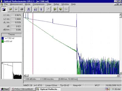
Connectors and splices are called “events” in OTDR jargon. Both should show a loss, but connectors and mechanical splices will also show a reflective peak so you can distinguish them from fusion splices. Also, the peak height will indicate the amount of reflection at the event, unless it is so large that it saturates the OTDR receiver. Then peak will have a flat top and tail on the far end, indicating the receiver was overloaded. The peak width shows the distance resolution of the OTDR or how close it can detect events.
OTDRs can also detect problems in the cable caused during installation. If a fiber is broken, it will show up as the fiber’s end much shorter than the cable or a high loss splice at the wrong place. If excessive stress is placed on the cable due to kinking or too tight a bend radius, it will look like a splice at the wrong location.
OTDR Limitations
The limited distance resolution of the OTDR makes it very hard to use in a LAN or building environment where cables are usually only a few hundred meters long. The OTDR has a great deal of difficulty resolving features in the short cables of a LAN and is likely to show “ghosts” from reflections at connectors, more often than not simply confusing the user.
Using The OTDR
When using an OTDR, there are a few cautions that will make testing easier and more understandable. First, always use a long launch cable, which allows the OTDR to settle down after the initial pulse and provides a reference cable for testing the first connector on the cable. Always start with the OTDR set for the shortest pulse width for best resolution and a range at least 2 times the length of the cable you are testing. Make an initial trace and see how you need to change the parameters to get better results.
Restoration
The time may come when you have to troubleshoot and fix the cable plant. If you have a critical application or lots of network cable, you should be ready to do it yourself. Smaller networks can rely on a contractor. If you plan to do it yourself, you need to have equipment ready (extra cables, mechanical splices, quick termination connectors, etc., plus test equipment.) and someone who knows how to use it.
We cannot emphasize more strongly the need to have good documentation on the cable plant. If you don’t know where the cables go, how long they are, or what they tested for loss, you will be spinning your wheels from the get-go. And it would help if you had tools to diagnose problems and fix them and spares, including a fusion splicer or some mechanical splices and spare cables. When you install cable, save the leftovers for restoration! And the first thing you must decide is if the problem is with the cables or the equipment using them. A simple power meter can test sources for output and receivers for input, and a visual tracer will check for fiber continuity. If the problem is in the cable plant, the OTDR is the next tool to locate the fault.
Fibre Optic Safety
Fibre Optics can be dangerous and damage your health and others around you. Care and consideration must be taken for yourself and others when working with fiber optic cabling and equipment.
Eye Safety
Optical sources used in fiber optics, especially LED’s used in premises networks, are of much lower power levels than used for laser surgery or cutting materials. Even the output of OTDRs, WDM, and fiber amplifier systems, which are much higher than LED systems, are still well below that used in laser surgery or machining.
The light that exits an optical fiber is also spreading out in a cone, so the farther away from the end of the fiber, your eye is, the lower the amount of power your eye receives. If you are using a microscope, which can efficiently focus all the light into your eye, it should have infrared filters to reduce the danger of invisible infrared light.
The infrared light in fiber optic links is at a wavelength that cannot penetrate your eye easily because the water absorbs it in your eyeball. Light in the 1300-1550nm range is unlikely to damage your retina but might harm the cornea or lens.
A typical laser pointer with a collocated beam (not expanding) and is at a visible wavelength (650nm) where the eye is transparent is probably more dangerous to the retina than a fiber optic link.
It’s not a good idea to look into a fiber unless you know no source is being transmitted down it. Since the light is infrared, you can’t see it, which means you cannot tell if there is light present by looking at it. You should always check the fiber with a power meter before examining it.
The real issue of eye safety is getting fiber scraps into the eye. As part of the termination and splicing process, you will be continually exposed to small scraps of bare fiber, cleaved off the fibers’ ends being terminated or spliced. These scraps are very dangerous. If they get into your eyes, they are very hard to flush out and will probably lead to a trip to the emergency room at the hospital. Whenever you are working with fiber, wear safety glasses!

Bare Fibre Safety
The broken ends of fibers and scraps of fiber created during termination and splicing can be extremely dangerous. The ends are extremely sharp and can easily penetrate your skin. They invariably break off and are very hard to find and remove. Sometimes a pair of tweezers and perhaps a magnifying glass will get them out. Most of the time, you have to wait to let them infect and work themselves out, which can be painful.
Be careful when handling fibers not to stick the broken ends into your fingers. Dispose of all scraps properly in a sharps bin. Some people keep a piece of double-stick tape on the bench to stick fiber scraps onto and then dispose of it in a sharps bin. Do not drop fiber scraps on the floor where they will stick in carpets or shoes and be carried elsewhere-like home!
Obviously, do not eat or drink anywhere near the work area. Fiber scraps can get into food or drink and be swallowed. The scraps can embed themselves in your digestive system and never be found.
Materials Safety
Fiber optic splicing and termination use various chemical cleaners and adhesives as part of the process. Normal handling procedures for these substances should be observed. If you are not certain of dealing with them, ask the manufacturer for a Material Safety Data Sheet (MSDS). Always work in well-ventilated areas. Avoid skin contact as much as possible, and stop using chemicals that cause allergic reactions. Even simple isopropyl alcohol, used as a cleaner, is flammable and should be handled carefully.
Fire Safety
Fusion splicers use an electric arc to make splices, so care must be taken to ensure no flammable gasses are contained in the space where fusion splicing is done. Splicing is never done in maintenance holes where gasses can accumulate. The cables are brought up to the surface into a splicing trailer where all fiber work is done. Of course, the splicing trailer is temperature-controlled and kept spotlessly clean to ensure good splicing.
Smoking should also not be allowed around fiber optic work. The ashes from smoking contribute to the dirt problems with fibers and the chance of explosions due to combustible substances.
Electrical Safety
Fiber cables are often installed around electrical cables, and care must be taken to prevent an electric shock. Many companies insist that any energy source is isolated when working on or near that equipment. The use of locks and tags is recommended.
The fusion splicer should be inspected and tested regularly for electrical safety, sometimes referred to as ‘Test and Tag.’ An electrician can complete this low-cost test in a short time.
Fibre Optic Installation Safety Rules
- Keep all food and beverages out of the work area. If fiber particles are ingested, they can cause internal hemorrhaging.
- Wear disposable aprons to minimize fiber particles on your clothing. Fiber particles on your clothing can later get into food, drinks, and/or be ingested by other means.
- Always wear safety glasses with side shields and protective gloves. Treat fiber optic splinters the same as you would glass splinters.
- Never look directly into the end of fiber cables until you are positive that there is no light source at the other end. Use a fiber optic power meter to make certain the fiber is dark. When using an optical tracer or continuity checker, look at the fiber from an angle at least 6 inches away from your eye to determine if the visible light is present.
- Work in well-ventilated areas.
- Contact wearers must not handle their lenses until they have thoroughly washed their hands.
- Do not touch your eyes while working with fiber optic systems.
- Keep all combustible materials safely away from the curing ovens.
- Put all cut fiber pieces in a safe place (a sharps bin)
- Thoroughly clean your work area when you are done.
- Do not smoke while working with fiber optic systems.
End of Fibre Optics Training Course
![]()
Well done, you have completed the Basic Fiber Optics training course. Your PDF course certificate is now available to download and save from your account.
✅ Add it to your resume, use it to your advantage to land that next job and standout from the rest!

Certificate Name
You can change the display name on your certificate in your user account.
Your Account >> Settings >> General

Downloads
You can download a copy of the Fiber Optics course notes here.
Support
Email support@satoms.com if you have any questions about this course or have any feedback on how we can make this course better, and don’t forget to leave us a course review 🙂
Follow us on LinkedIn and Facebook for the latest updates and free courses!
Thanks,
Satoms Training Team
Click the ‘Complete’ and then ‘Finish Course’ buttons below at the end of a lesson to mark that lesson as completed in your user dashboard.


Comments
Post a Comment